ELECTRONIC SPEED CONTROL (36V)
Page F-6
Repair and Service Manual
Read all of Section B and this section before attempting any procedure. Pay particular attention to all Notes, Cautions and Warnings
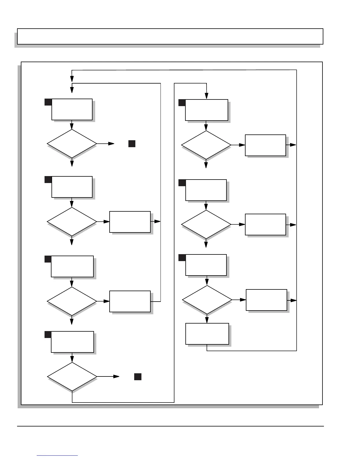
Fig. 8 Detailed Troubleshooting Diagram (Sheet 2 of 8)
Verify Continuity -
Replace Microswitch
Reference Voltage?
Yes
No (Zero)
No (Zero)
Disconnect Charger Harness Red Wire
From Charger Receptacle Small White Wire
Correct Harness
Red Wire Problem;
Reconnect Wires
Reference Voltage?
Yes
Voltage Between
Battery B- &
Charger Receptacle
Small White Wire
No (Zero)
Remove Charger Receptacle Cover
Replace Reed Switch;
Reassemble
Reference Voltage?
Yes
Voltage Between
Battery B- &
Charger Receptacle
Positive Pin
Correct Charger Harness
Large White Wire
Problem
Reassemble
Reference Voltage?
Yes
No (Zero)
Key ON, Direction Selector in F
Voltage Between Battery
B- & Direction Selector
Microswitch
Terminal w/ Blue Wire
Voltage Between Battery
B- & Direction
Selector Microswitch
Terminal with Red Wire
Key ON, Direction Selector in F
Key ON, Direction Selector in F
Pedal depressed
Key ON, Direction Selector in F
Pedal depressed
Solenoid
Clicks?
Yes
Depress
Pedal
Voltage Across Small
Terminals on Solenoid
Replace Solenoid
No
Reference Voltage?
Yes
No (Zero)
Replace Small Black
Wire (Small Terminal
on Solenoid to
Controller B-)
Reference Voltage?
Yes
No (Zero)
Voltage Between
Battery B- &
Small Solenoid Terminal
With 2 Red Wires
Go to
22
Go to
13
6
7
8
9
10
11
12
 Loading...


