ELECTRONIC SPEED CONTROL (36V)
Page F-7
Repair and Service Manual
Read all of Section B and this section before attempting any procedure. Pay particular attention to all Notes, Cautions and Warnings
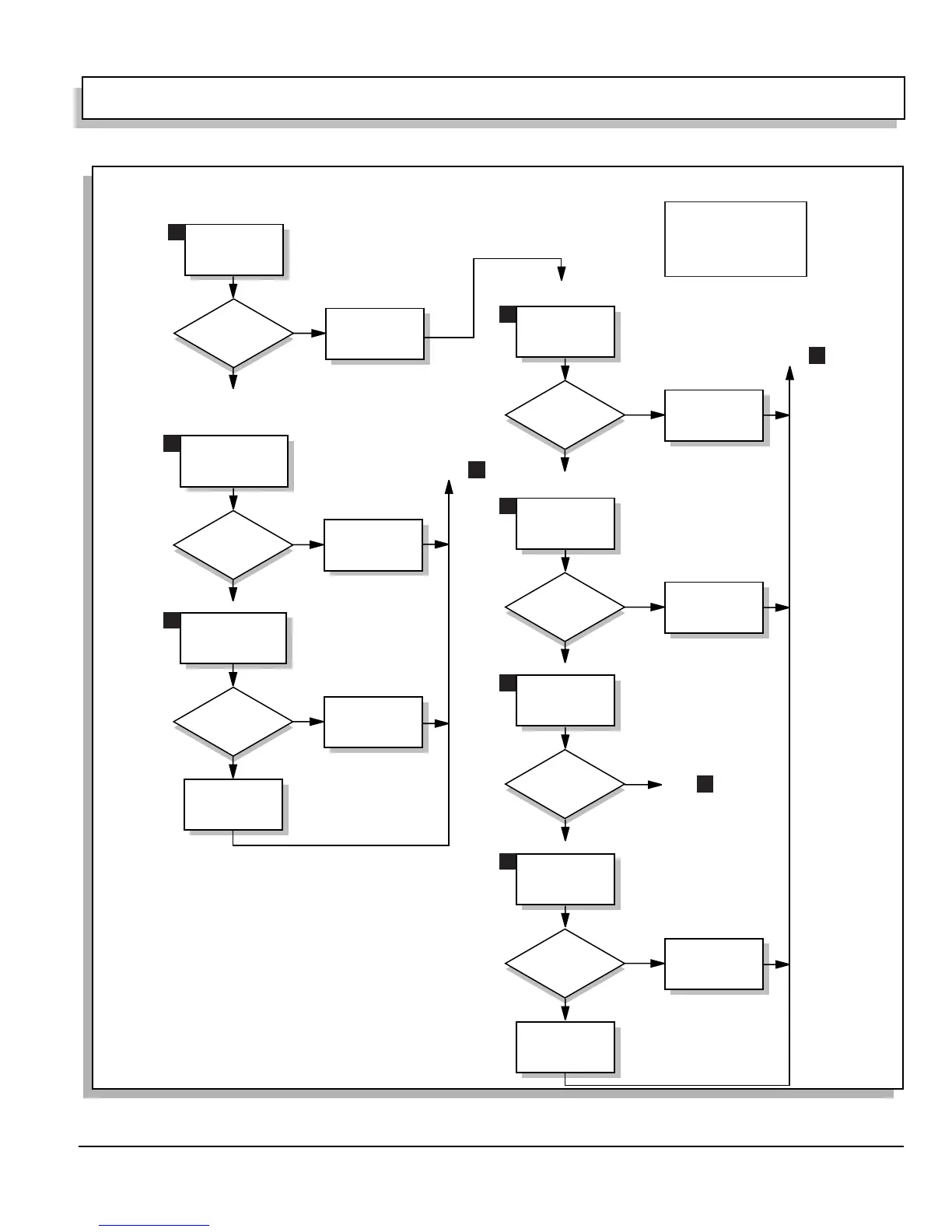
Fig. 9 Detailed Troubleshooting Diagram (Sheet 3 of 8)
Key ON, Direction Selector in F
Pedal Depressed
Key ON, Direction Selector in F
Pedal Depressed
Correct Problem In
Red Control Harness
Wire
Reference Voltage?
Yes
No (Zero)
Battery B- to Back Side
of Control Harness
4-Pin Connector
(Pin With Red Wire)
Correct Problem In
4-Pin Connector
Assembly
Reference Voltage?
Yes
No (Zero)
Battery B- to Back Side
of Pedal Box Harness
4-Pin Connector
(Pin With Red Wire)
Correct Problem in
4-Pin Connector
Assembly
Reference Voltage?
Yes
Reference Voltage?
Yes
No (Zero)
No (Zero)
Battery B- to Back Side
of Pedal Box Harness
4-Pin Connector
(Pin With Green Wire)
Key ON, Direction Selector in F
Key ON, Direction Selector in F
Battery B- to Back Side
of Control Harness
4-Pin Connector
(Pin With Green Wire)
Correct Problem In
Green Control
Harness Wire
The 4-pin connector is a
very difficult item to check.
Check both sides of connector
first, and then, only if necessary,
open the encapsulated connector
and check the connections.
Disconnect Key Switch Harness
Green Wire From Control Harness
Key On, Direction Selector in F
Reconnect Key Switch Harness
Remove Gauge Plate From
Instrument Panel
Key On, Direction Selector in F
Reconnect Key Switch
Harness
Reference Voltage?
Yes
No (Zero)
Voltage Between
Battery B- &
Green Key Switch Wire
Correct Green Key
Switch Harness Wire
Problem
Reference
Voltage?
Yes
No (Zero)
Voltage Between Battery
B- & Key Switch Terminal
With Green Key Switch
Harness Wire
Replace Key Switch;
Reassemble
Reference Voltage?
Yes
No (Zero)
Voltage Between Battery
B- & Key Switch Terminal
With Blue Key Switch
Harness Wire
Correct Problem In
Blue Key Switch
Harness Wire;
Reassemble
Direction Selector in F
Return to
6
Return to
6
13
14
15
16
17
18
19
Go to
20
 Loading...


