ELECTRONIC SPEED CONTROL (48V)
Page F-24
Repair and Service Manual
Read all of Section B and this section before attempting any procedure. Pay particular attention to all Notes, Cautions and Warnings
TROUBLESHOOTING DIAGRAMS
The following diagrams will assist in servicing the vehi-
cle. By utilizing the Fault Codes, considerable time will
be saved in determining the probable vehicle operating
malfunction. The vehicle power and control wiring dia-
gram is included for your convenience in tracing the elec-
trical wiring (Ref Fig. 9 on page F-27). The following 6
flow charts will assist in diagnosing and correcting prob-
lems not diagnosed through the Fault Codes.
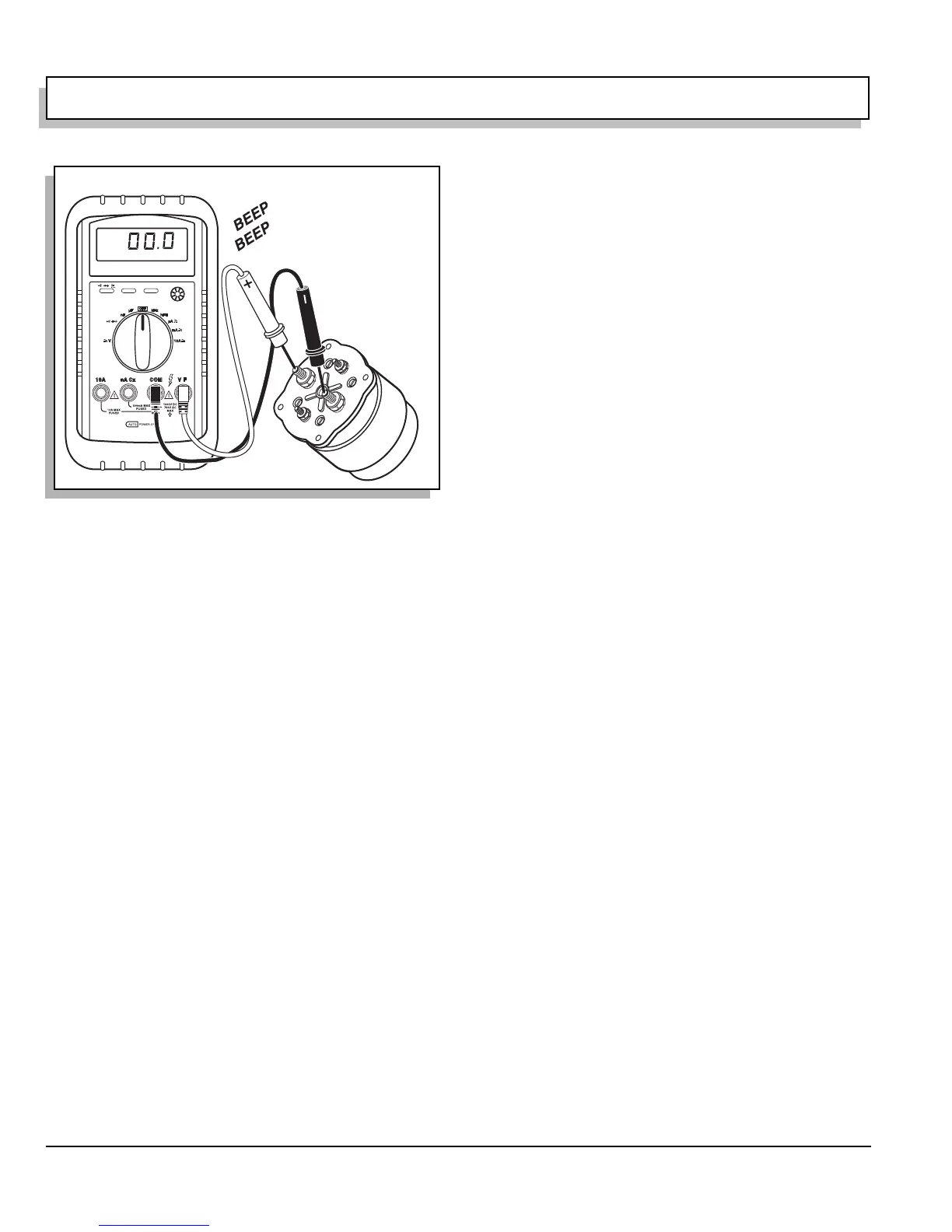
Fig. 6 Continuity Check of Solenoid

 Loading...


