- 13 -
2.3 Installation
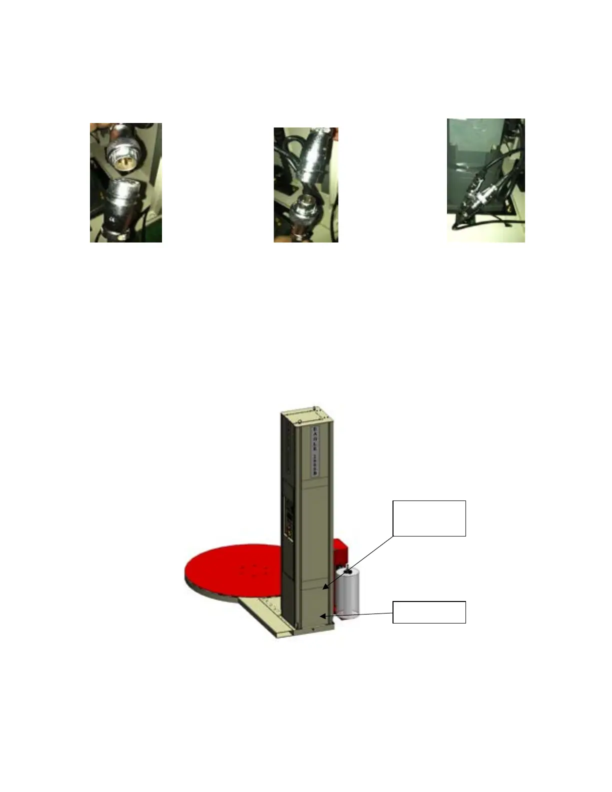
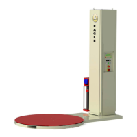
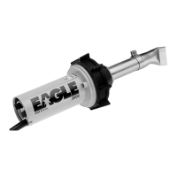
Step 6 - Insert the connector plug inside the bottom of the mast into the corresponding receptacles.
(See Fig 2-9a, 2-9b, 2-9c)
Fig. 2-9a
Fig. 2-9b
Fig. 2-9c
Note: These connectors are for carriage motor power (pre-stretch), photo-electric eye, home limit
switch, and E-Stop switch located on the bottom of the carriage.
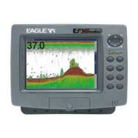
Step 7 - Fasten the lower rear panel into the corresponding position on the post using the pin. (See Fig.
2-10)
Fig. 2-10
Step 8 - Verify that all screws are tight and then turn on the power. Check to see if the power
indicator is on and that text is displayed on the LCD screen.