4810 Clover Road • Greensboro, NC 27450 • 1-800-336-2776 • www.eagleequip.com • © Eagle Equipment 2017.12 • page 11
4. INSTALLATION
4.1 OPENING AND INSPECTION
Open the package and inspect for any damaged parts. If there are any questions, please do not use the
equipment and contact Eagle Equipment Customer Service (1-800-336-2776). Standard accessories with
equipment are shown as follows:
Screw stud of drive axis 1
Balancing pliers 1
Allen wrench 1
Measure caliper 1
Quick release nut 1
Adapter (cone) 4
Counter weight (100g) 1
Protection hood (optional) 1
4.2 INSTALLING MACHINE
1. The balancer must be installed on the solid cement or similar ground. Unsolidied ground can
bring measuring errors.
2. There should be 20" around the balancer in order to operate conveniently.
3. Nail anchor bolts on the base’s mounting hole of balancer to secure the balancer.
4.3 INSTALLING OPTIONAL HOOD
Install the wheel hood on the equipment by insert the pipe of protection hood into the hood shaft
behind the cabinet, then fasten them with M10×65 screws from the spare parts box
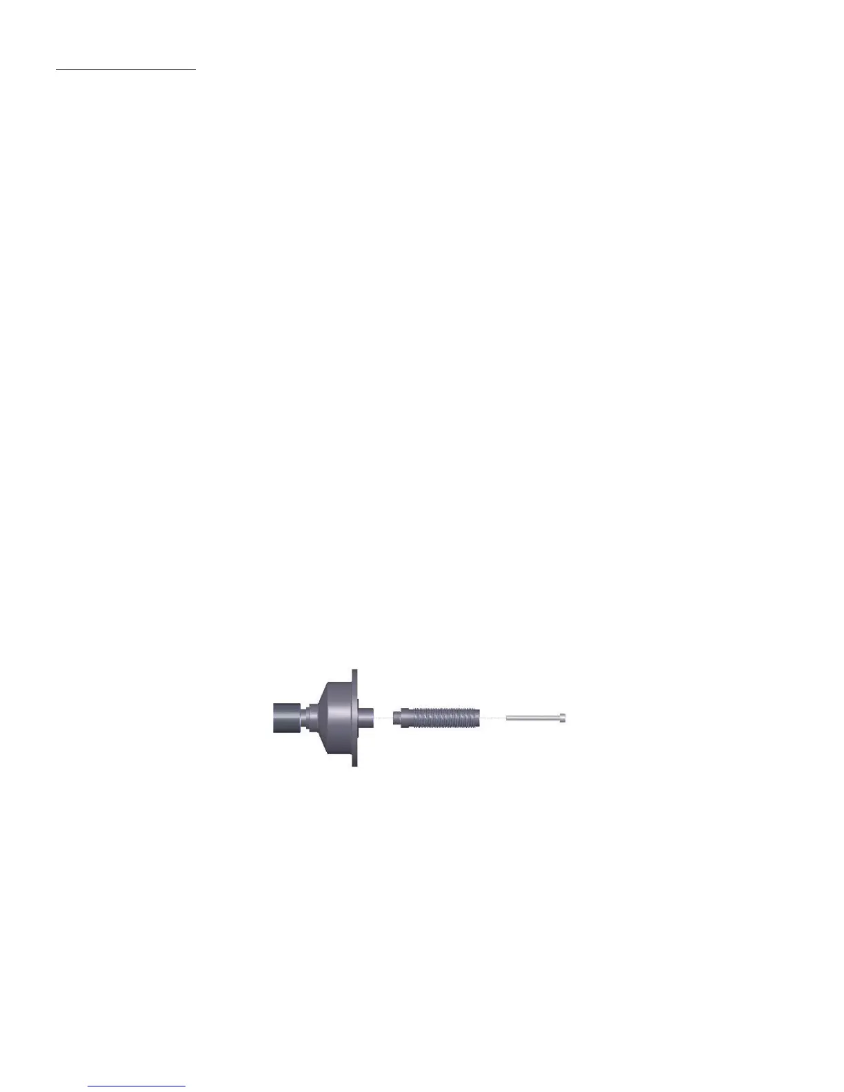
4.4 INSTALLING SCREW STUD OF DRIVE AXIS
Install screw stud of drive axis on the main axis with M10 × 150 socket bolt, then screw the bolt. (Refer
to Figure 4-1)
(Notice: a wheel can be installed on the main axis before screwing bolt, then hold the wheel by hands
in order to prevent the main axis from revolving together with the bolt.)
Figure 4-1