4810 Clover Road • Greensboro, NC 27450 • 1-800-336-2776 • www.eagleequip.com • © Eagle Equipment 2017.12 • page 27
PRECISION CHECKING TIP:
Input right wheel data (a. b. d value), preform machine self-calibration, press START to begin the
balance operation. Make a note of rst results, clip the 100 gram counterweight on the outside edge
of wheel (when outside indicator lights are all on is top zenith position), press START again to begin
the balance operation. This cycle displays in addition to the rst cycle, should amount 100±2. Slowly
turn the wheel manually, when the outer lights are all on, check that the 100 gram counterweight is
at the 6 o’clock tire position. If the 100 gram counterweight is not at the 6 o’clock tire position (or the
weight does not equal 100 grams), the balancer may indicate there is a problem with a precise reading.
If the amount is 100 grams, follow the same method to run the balancing cycle. Check to ensure the
weight is 100 gram and at the 6 o’clock tire position.
18. MAINTENANCE
DAILY MAINTENANCE
Before the maintenance, please switch off
the power-supply.
1. Adjust the tension of the belt.
- Dismantle the top cover hood.
- Unscrew motor screw, move the motor
until the belt’s tension is proper, and
emphatically press the belt
downwards about .15" (4mm).
- Screw motor screw and install the top
cover hood.
2. Check whether the wires of electricity
part connects are reliable.
3. Check whether the screw stud of the main shaft is loose.
- Locking nut can not x wheel tighten on main shaft
- Use hexagonal wrench to tighten the screw stud of the main shaft.
PROFESSIONAL MAINTENANCE
1. If the imbalance amount of the tested wheel has an obvious error (the amount is too big) and can
not be improved after self-calibrating, the parameter in the machine has changed and needs to be
professionally corrected.
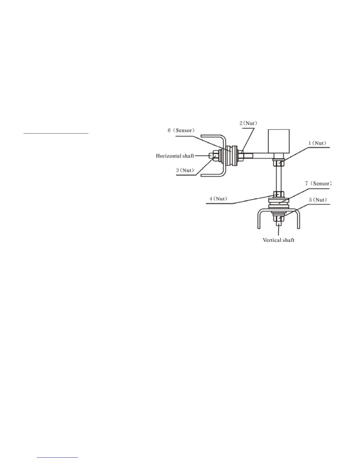
2. Replacing and adjusting the pressure sensor should be done by professionals as per the following
methods:
1. Unscrew the No. 1, 2, 3, 4, 5 nuts.
2. Dismantle the sensor and screw stud.
3. Replace No. 6, 7 the sensor components.
4. Install the sensor and the screw stud. Be sure to pay attention to the sensor’s direction.
5. Screw No. 1 nut until it is tight.
6. Screw the No.2 nut to make the main shaft and the ank of cabinet vertical, and then screw the
No.3 nut tightly.
7. Screw the No.4 nut (not so tightly), then screw No.5 nut.
3. The circuit board and its components should be replaced by professionals.
Figure 18-1