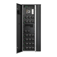
Cable entry to the UPS is always on the top, the bottom or the rear of the cabinet.
NOTE: Follow the installation instructions given in Section 4.4.3 UPS system power wiring preparations.
NOTE: The frame of the external battery cabinet must be grounded to the UPS. If the distance between the
UPS and external battery cabinet is less than 500 mm, a separate EMI grounding between the two
cabinets is needed. The shipping/fixing bracket mounted to the front side of the UPS has two alternative
grounding cable fixing points for this purpose. See Figure
19: EMI grounding point to external battery
cabinet. Other end of the cable is connected to the closest available point in the chassis of the external
battery cabinet. The connection point must be unpainted, and provide reliable mechanical and electrical
contact to the chassis. For the cable size, refer to Table
10: Minimum recommended multi-core cable and
fuse sizes for battery connection.
Figure 19. EMI grounding point to external battery cabinet
1. EMI grounding points
55..55 IInnssttaallll aa rreemmoottee EEPPOO sswwiittcchh
You can use a remote EPO switch in case of an emergency to shut down the UPS and remove power to
the critical load from a location away from where the UPS is installed.
EPO is connected to the UPS's top front panel, on connector EPO. Figure
20: Connections of the EPO
switch shows the NO and NC connections of the EPO switch.
EPO connector (front view):
• A = Normally open
• B = Normally closed
EATON 93PM G2 UPS USER’S AND INSTALLATION GUIDE P-164000956
-
February 2021 www.eaton.eu 5522

 Loading...