Do you have a question about the Eaton Callisto 5PX RT G2 and is the answer not in the manual?
Defines the purpose of the service manual for technicians to diagnose, troubleshoot, and repair UPS products.
Outlines the global process for handling broken products, from customer issue to repair and return.
Presents block diagrams and topology schematics for UPS system components.
Details critical safety measures, including disconnecting power, avoiding live parts, and discharging capacitors.
Illustrates the wiring and connector relationships between major UPS boards and external components.
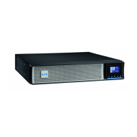
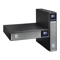
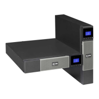
Provides photographic views showing the actual internal component layout and connections for different UPS models.
Shows the connection diagram for the EBM (External Battery Module) for 48/72V systems.
Lists Printed Circuit Board Assemblies (PCBAs) with their model names, PQNA, and new part numbers.
Details the functions and schematics of the PSDR (Power Supply DC/DC, DC-AC Inverter) and IO boards.
Describes the functions of the Control (CNTL) board, including DSP control and component detection.
Explains the functions of the Communication (COMM) and EPO (Emergency Power Off) board.
Details the LCD display, its indicators, buttons, and front panel layout.
Lists and describes UPS alarm codes, messages, and their general descriptions.
Provides a table of fault codes, messages, descriptions, and diagnostic guidance for UPS failures.
Guides on how to locate faulty functions or components using the UPS display and fault information.
Defines the rules and criteria for distinguishing between alarms and faults displayed on the LCD.
| Power Rating | 1500 VA |
|---|---|
| Form Factor | Rack/Tower |
| Dimensions (H x W x D) | 3.5 x 17.2 x 19.0 inches |
| Weight | 50 lbs |
| Topology | Line-interactive |
| Display | LCD |
| Frequency | 50/60 Hz |
| Battery Type | Lead-acid |
| Communication | USB, Serial |
| Typical Recharge Time | 3 hours to 90% capacity |
| Communication Ports | USB, RS-232 |