Summary
1 Introduction ...................................................................5
1.1 Purpose of the document.................................................................................. 5
1.2 Analysis process ............................................................................................... 6
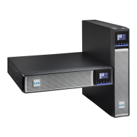
1.3 Schematic of the UPS ........................................................................................ 7
2 Security ........................................................................10
3 Interconnection diagram of products by power
rating. ..............................................................................12
3.1 UPS interconnection diagram ..........................................................................12
3.2 UPS interconnection Actual .............................................................................15
3.3 EBM interconnection diagram .........................................................................21
4 Diagrams showing the location of each principle
function on the circuit and the assembled board .......22
4.1 PCBA list ...........................................................................................................22
4.2 PSDR and IO schematic ...................................................................................23
4.2.1 PSDR and IO board ............................................................................ 34
4.3 CNTL ..................................................................................................................35
4.4 COMM & EPO ....................................................................................................36
4.5 LCD ....................................................................................................................37
5 Failure analysis ...........................................................38
5.1 Alarms ...............................................................................................................38
5.2 Fault ...................................................................................................................38
5.3 Location of the faulty function or component ................................................39
5.4 LCD Fault and Alarm messages ......................................................................51
6 Disassembly ................................................................52
7 Component level Tests by function and by board ...57
 Loading...