EasyManua.ls Logo

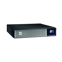
Eaton Callisto 5PX RT G2 - 3 Interconnection diagram of products by power rating; 3.1 UPS interconnection diagram

Eaton Callisto 5PX RT G2
60 pages
To Next Page IconTo Next Page
To Previous Page IconTo Previous Page
Loading...
Title
Callisto 5PX G2 Service Manual
Checked
:
Rev:
Approved
:
Confidential
This specification is the property of Eaton Corp. and shall not be reproduced or copied or used as the basis for manufacture or sale of apparatus without permission
3 Interconnection diagram of products by
power rating.
Goal: To know the interconnections and connectors between the boards for
different power ratings of products.
3.1 UPS interconnection diagram
EPO
BOARD
COMM
BOARD
PSDR BOARD
Internal Battery
LCD
CNTL BOARD
IP-L
IP-N
FAN
USB
RS232
Segment
1
Segment
2
Input
Socket
EBM
Output
Socket
CARD
Box
RJ45
OP-L
OP-N
Segment
+
-
+
-
EPO & Dry in
Dry out
+
-
For Internal Lithium battery
communication
1
2
3
4
5
6
8
9
7
10
11
12
13
14
15
17
18
19
20
21
NTC BAT
NTC HS
22
23
Main
Fig3.1: 1000~1500VA (230V) interconnection Block

Related product manuals