IB01602002E
Page 19
Effective 10/02
6.2.1 TRANSFER SWITCH APPEARS INOPERATIVE
Step 1: Verify that all plugs and sockets are properly
interconnected.
Step 2: Verify that the correct system voltage appears
at NORMAL switch. Measure the voltage at the
breaker lugs.
Step 3: Verify that the voltage selection plug is in the
proper position to match the system voltage.
Step 4: Look for any obviously burned components.
Determine the cause and rectify, if possible.
Replace defective components after the cause
is determined.
Step 5: This step is for closed transition only. Refer
to Figure 5-3 for manual operating instructions.
Verify whether or not thesystem voltage now
appears on the load terminals.
If YES: Proceed to check logic for problems
in respective logic instruction book.
If NO: Check all power connections and
the switching mechanism.
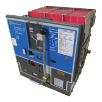
Step 5: This step is for open transition only. Press
the push-to-close button on the normal switch-
ing device (Figure 5-2). Verify whether or not
thesystem voltage now appears on the load ter-
minals.
If YES: Proceed to check logic for problems
in respective logic instruction book.
If NO: Check all power connections and
the switching mechanism.
6.2.2 TRANSFER SWITCH WILL NOT AUTOMATI-
CALLY TRANSFER TO NORMAL
Step 1: Check for proper line voltage on N1, N2, N3.
Step 2: Is the normal switching device charged?
If YES: Continue with other procedures.
If NO: Go through section 6.2.4 first before
continuing.
Step 3: Is the emergency switch OPEN?
If YES: Proceed to Step 5.
If NO: Proceed to Step 4.
Step 4: Measure voltage between terminals A9 and A8
on the emergency switching device (shunt trip).
Does the voltage measure 120 VAC ±10 volts?
Record reading.
If YES: Check shunt trip in emergency switch.
If NO: Check wiring to A9 and A8.
Step 5: Measure voltage between terminals A1 and A2
on the normal switching device (spring release
coil). Does the voltage measure 120 VAC ±
10 volts? Record reading.
If YES: Check spring release coil in normal
switching device.
If NO: Check wiring to A1 and A2.
6.2.3 TRANSFER SWITCH WILL NOT AUTOMATI-
CALLY TRANSFER TO EMERGENCY
Step 1: Check for proper line voltage on E1, E2, E3.
Step 2: Is the emergency switching device charged?
If YES: Continue with other procedures.
If NO: Go through Section 6.2.4 first before
continuing.
Step 3: Is the normal switching device OPEN?
If YES: Proceed to Step 5.
If NO: Proceed to Step 4.
Step 4: Measure voltage between terminals A9 and A8
on the normal switching device (shunt trip).
Does the voltage measure 120 VAC ± 10 volts?
If YES: Check shunt trip in normal switch
If NO: Check wiring to A9 and A8.
 Loading...
