O & M Manual IM05805019K EATON Diesel Plus
Effective June 2011 Diesel Engine Fire Pump Controller
2 EATON CORPORATION www.eaton.com
Contents
Description Page Description Page
1. INTRODUCTION ............................................................. 3
1.1 Safety......................................................................... 3
1.2 Warranty ..................................................................... 3
1.3 Safety Precautions........................................................ 3
1.4 Product Overview ......................................................... 3
2. INSTALLATION AND ELECTRICAL CONNECTIONS ............... 3
2.1 Mounting..................................................................... 3
2.2 Pressure Sensor Connections ......................................... 3
2.3 Electrical Connections ................................................... 3
2.3.1 Wire Sizes .......................................................... 4
2.4 System Pressure Connection.......................................... 4
3. HARDWARE DESCRIPTION .............................................. 4
3.1 General ....................................................................... 4
3.1.1 Battery Chargers ................................................. 4
3.1.2 Three Step Charge............................................... 4
3.1.3 Charger Shut Down ............................................. 4
3.1.4 AC Input Fuse Protection...................................... 5
3.1.5 Battery Charger Display........................................ 5
3.1.6 Charger Setup: Lead Acid / NiCad .......................... 5
3.1.7 Forced Charging .................................................. 5
3.1.8 Specifications ..................................................... 5
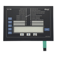
3.2 Front Operator Panel ..................................................... 5
3.2.1 The LEDs ............................................................ 6
3.2.2 Pushbuttons ....................................................... 7
3.3 Display Board Access Area ............................................ 7
3.4 Power I/O Board ........................................................... 7
3.5 Engine Board................................................................ 7
3.6 External Pushbuttons .................................................... 7
3.6.1 Stop .................................................................. 7
4. OPERATION................................................................... 7
4.1 General ....................................................................... 7
4.2 Start Sequence ............................................................ 8
4.2.1 Manual Start Sequence ........................................ 8
4.2.2 Automatic Start Sequence .................................... 8
4.2.3 Run Period Timer ................................................. 8
4.2.4 Sequential Start Timer.......................................... 8
4.3 Program Descriptions .................................................... 9
4.3.1 Control Inputs ..................................................... 9
4.3.2 Control Input Descriptions .................................... 9
4.3.3 Loss of DC Power ................................................ 9
4.3.4 Speed Switch Malfunction .................................... 9
4.3.5 Engine Starter Coil Failure ..................................... 9
4.3.6 Audible Alarm Silencing........................................ 9
4.3.7 Power Failure Alarm ............................................10
4.4 Output Relays............................................................. 10
4.4.1 Relay Functions ................................................. 10
4.4.2 Future #1 - Future # 2 ........................................ 10
4.4.3 Engine Alarm Functions ...................................... 10
5. PROGRAMMING ........................................................... 10
5.1 Introduction ............................................................... 10
5.2 Navigation.................................................................. 10
6. HISTORY, DIAGNOSTICS, STATISTICS,
CONFIGURATION..............................................................14
6.1 System History ...........................................................14
6.2 Statistics ...................................................................14
6.3 Controller Diagnostics..................................................15
7. COMMUNICATION ........................................................15
7.1 USB ..........................................................................15
7.1.1 Information Download ........................................15
7.1.2 Custom Message Upload.....................................15
7.1.3 Firmware Update................................................15
7.1.4 Language Upload ...............................................15
7.2 Embedded Webpage (Optional) .....................................15
7.3 RS485 Serial Port (Optional).........................................15
7.4 RS232 Serial Port (Optional).........................................15
8. CUSTOM MESSAGES ....................................................16
APPENDIX A: MAIN MENU TREE ........................................17
APPENDIX B: REGIONAL SETTINGS MENU TREE..................18
APPENDIX C: PRESSURE SETTINGS MENU TREE .................19
APPENDIX D: TIMER VALUES MENU TREE..........................20
APPENDIX E: CUSTOM INPUT/OUTPUT MENU TREE ............21
APPENDIX E(a): CUSTOM INPUTS MENU TREE....................22
APPENDIX E(b): CUSTOM OUTPUTS MENU TREE ................23
APPENDIX E(c): CUSTOM LIGHTS MENU TREE ....................24
APPENDIX F: MAIN MENU PASSWORD MENU TREE ............25
APPENDIX G: CUSTOM MESSAGE LOAD & ACTIVATION .....26
APPENDIX K: ...................................................................27
APPENDIX L: ALARM/STATUS MESSAGES .........................28
9. INITIAL START UP ........................................................29
9.1 Automatic Start Test....................................................29
9.2 Manual Start Test........................................................29
9.3 Engine Test ................................................................29
9.4 Weekly Exerciser Test ..................................................30
 Loading...


