O & M Manual IM05805019K EATON Diesel Plus
Effective June 2011 Diesel Engine Fire Pump Controller
6 EATON CORPORATION www.eaton.com
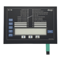
The Diesel Plus Controller front panel serves two primary
functions: output and input. The output function consists of:
• A four-line, 40 character LCD display module
• Twenty Four LED outputs:
Engine Run Interlock On
Remote Start Speed Switch Fault
Deluge Valve ECM Selector in Alt. Position
Low Pressure Fuel Injection Malfunction
Fail to Start Low Fuel
Charger #1 Failure Low Suction Pressure
Charger #2 Failure Low Oil Pressure
Battery #1 Failure Engine Overspeed
Battery #2 Failure High Engine Temperature
Six (6) user defined LEDs.
There are nine input functions accessible via the pushbuttons:
• Silence Alarm
• Engine Test
• Data | Print
•Lamp Test
• Reset | Save/Exit
•Up
•Down
•Ack. Alarm
•Menu
A four-line, 40-character alphanumeric LCD Display module is
used to display all Diesel Plus monitored parameters, set
points, and messages in easy to read formats. The display has a
green high contrast background that allows clear visibility of
any information displayed. The display is continuously lit for
clear visibility under poorly lit or no light conditions.
Seven different displays can be presented via the LCD display:
• Status Display
• Set Points Display
• Statistics Display
• Diagnostics Display
•History Display
• Data/Print Display
• Message History Display
The “Home” screen display will show the current date and
time, current pressure, Battery #1 voltage and charging amps,
Battery #2 voltage and charging amps and whether Automatic
Shutdown is in ON or OFF mode.
The fourth line of the display indicates the time remaining on
any active timers, alarms without an associated LED, and
custom messages.
3.2.1 The LEDs
• Engine Run - This green LED will be illuminated when there is
an Engine Run signal from the engine.
• Remote Start - This green LED will be illuminated after
receiving a start signal on the remote start input.
(Terminals 11 and 34)
• Deluge Valve - This green LED will be illuminated after
receiving a start signal from special starting equipment. This
is a normally closed contact that is required to be opened to
start. A factory installed jumper wire must be removed to use
these contacts. (Terminals 11 and 35)
• Low Pressure - This green LED will flash when the system
pressure has dropped below the programmed low pressure
alarm set point. This LED will be fully illuminated when the
pressure falls below the pressure start point.
• Fail to Start - This red LED will be illuminated if the controller
has not received an engine run signal from the engine after
attempting to crank the engine a total of 6 times
• Battery # 1 Failure - This red LED will be illuminated during
the cranking cycle when the controller detects a weak or
discharged battery, i.e. 67% of rated voltage, or less, or
whenever a battery cable is disconnected.
• Battery # 2 Failure - This red LED will be illuminated during
the cranking cycle when the controller detects a weak or
discharged battery, i.e. 67% of rated voltage, or less, or
whenever a battery cable is disconnected.
• Charger # 1 Failure - This red LED will be illuminated when
the supply power to the charger is lost or when the charger
malfunctions. The engine continues to run. To avoid nuisance
alarms, the AC Power Failure Alarm set point can be
increased.
• Charger # 2 Failure - This red LED will be illuminated when
the supply power to the charger is lost or when the charger
malfunctions. The engine continues to run. To avoid nuisance
alarms, the AC Power Failure Alarm set point can be
increased.
• Interlock On - This green LED will flash when the interlock
input is received, signaling that another controller or device
has locked out the controller. (Terminals 11 and 39)
• Speed Switch Fault - This red LED will be illuminated if the
controller is running, the engine run signal is lost and the oil
pressure does not drop. (Terminals 2 and 4)
• ECM Selector in Alt. Position - This red LED will be illuminated
when the controller receives a signal from the engine
indicating the engine is running on the alternate ECM.
(Terminal 301)
• Fuel Injection Malfunction - This red LED will be illuminated
when the controller receives a signal from the engine
indicating there is a fuel injection malfunction. (Terminal 302)
 Loading...


