EATON Diesel Plus O & M Manual IM05805019K
Diesel Engine Fire Pump Controller Effective June 2011
EATON CORPORATION www.ceaton.com 29
9. INITIAL START UP
Ensure that circuit breakers CB1 and CB2 are in the OFF (0)
position.
Ensure that AC power is supplied to terminals L and N, and G is
grounded.
Connect engine batteries to the controller, terminals 6, 8 and 11.
If batteries are connected in wrong polarity the battery voltage
will read zero.
Turn circuit breakers CB1 and CB2 ON (“1” position).
Pressure (start) is factory preset at 1 PSI.
Turn the mode selector switch to the “OFF” position
Ensure that the Diesel is programmed to user’s specifications.
Refer to section 5 in this manual.
9.1 Automatic Start Test
Turn the mode selector switch to the “AUTO” position.
Ensure that water pressure is available and the LCD display on
the display panel is reading the system pressure correctly.
Decrease water pressure below the programmed start point.
The controller will begin its cranking cycle.
Should the engine fail to start after 6 crank and rest cycles, the
audible alarm will sound and the “Fail To Start” annunciator
will illuminate. Turning the mode selector switch to the “OFF”
position will silence the alarm.
When engine starts, “Engine Run” annunciator illuminates.
Increase water pressure above programmed START point.
Press the stop pushbutton on the enclosure. If the pressure is
satisfied, and there are no other starting conditions the engine
will stop.
OR
If Auto Stop is programmed for "On", the engine will stop
automatically after the Run Period Timer times out and pressure
is satisfied. The RPT is programmed by the user; the factory
setting is 30 minutes.
If the Sequential Timer is > 0 seconds, automatic start will be
delayed by the number of seconds programmed.
9.2 Manual Start Test
Turn the mode selector switch to the “Manual” position
Press the Crank #1 pushbutton. The Engine will crank and start,
the “Engine Run” annunciator will illuminate.
Pres the STOP pushbutton. Wait for the engine to stop. Turn the
mode selector switch to the “Manual” position.
Press the Crank #2 pushbutton. The Engine will crank and start,
the “Engine Run” annunciator will illuminate.
Press the STOP pushbutton. The engine will stop. The engine
will stop.
9.3 Engine Test
To run a manual test, depress the "Engine Test" button on the
keypad. Then press ACK. The Drain Valve Solenoid will energize
and drop the pressure on the controller to zero. The controller
will start the engine automatically. The “Engine Run”
annunciator will illuminate.
Press the STOP pushbutton.
The engine will stop.
NOTE
Engine will shutdown if Low Oil Pressure, High Water Temp or Overspeed
alarms are detected during the engine test.
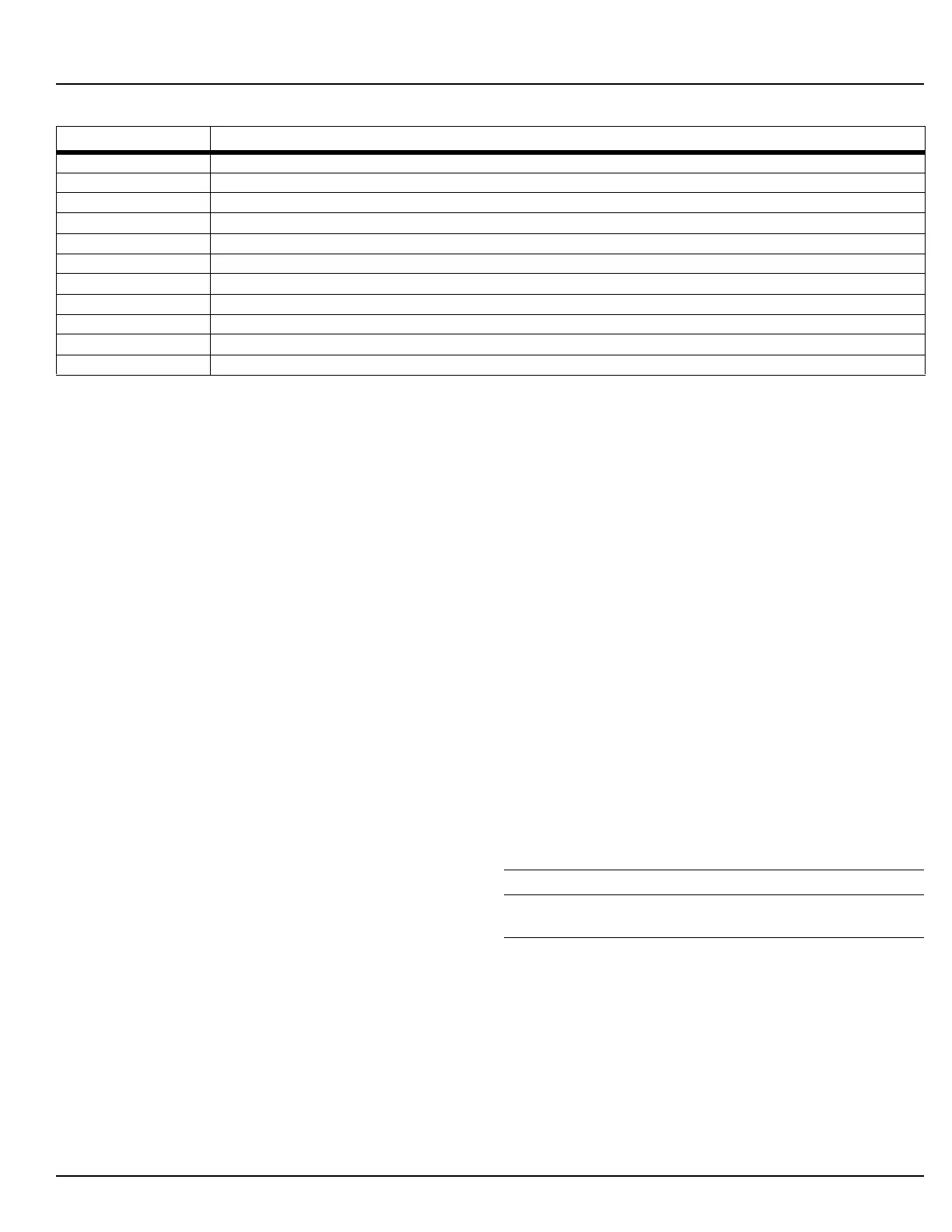
RPT Timed Out The running period timer has finished its timing cycle
RPT Stopped The Run Period Timer has finished timing or been cleared.
Speed SW Malfunction The engine run signal has been removed prior to the controller initiating a stop.
SST Started The sequential start timer has started timing.
SST Stopped The sequential start timer has finished timing or been cleared.
System Startup Power has been reapplied to the system and a successful system boot has been completed
Transducer Fail The controller has detected that the transducer has failed
Weekly Test Done The weekly test has been completed
Weekly Test Fail A Weekly test has been initiated, however the engine has failed to start.
Weekly Test Start The engine has started on a weekly test
Weekly Test Stop The Weekly Test Cycle timer has been cleared.
APPENDIX L: ALARM/STATUS MESSAGES (Continued)
Message Description
 Loading...


