For more information visit: www.cutler-hammer.eaton.com
Page 5-3
Effective 10/02 IL17562BH04
Explanation of Ct Ratio Presentation
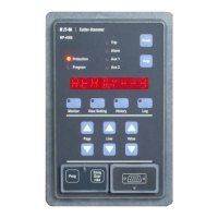
The MP-3000 motor relay is available in multiple styles designed for
use with current transformers (Cts) having a nominal or rated
secondary current of either 5 amperes or 1 ampere. Check the relay
labeling or the catalog number, and the Ct secondary rating, to
confirm a match.
All displayed information is the same for either of the two types of MP-
3000 relays. When Ct ratios are to be set, the value entered is the
numerator of the main Ct ratio. The denominator is assumed to be
either 5 or 1, depending on the rating of the cts and relay in use.
For example, a set of three 400:5 phase Cts might be used with an
MP-3000 specified for 5 A Cts. The phase Ct ratio is then set to 400.
Alternatively, a set of three 400:1 Cts could be used with an MP-3000
rated for 1 A cts. Use a setting of 400 in this case as well.
Ct Ratio Selection
Check the following criteria to insure a suitable current transformer ratio.
For a 5 ampere Ct set:
For optimum metering accuracy at low loads, the Ct should deliver
between 3.5 and 4 amperes at 100 percent FLA. Attempt to achieve
3.75 A.
For reliable motor protection, the Ct must deliver between 2.5 and 4
amperes at 100 percent FLA.
For example, if the motor has an FLA value of 300A, a 400:5 Ct will supply:
300 × 5/400 = 3.75 amperes, an ideal value.
For a 1 ampere Ct set:
For optimum metering accuracy at low loads, the Ct should deliver
between 0.7 and 0.8 amperes at 100 percent FLA. Attempt to achieve
0.75 A.
For reliable motor protection, the Ct should deliver between 0.5 and
0.8 amperes at 100 percent FLA.
For example, if the motor has an FLA of 300A, a 400:1 Ct will supply:
300 × 1/400 = 0.75 amperes, an ideal value.
Note that FLA/PCt must lie between 0.25 and 1.5 for successful
programming — you will not be able to exit Program Mode until one
or the other value is adjusted. See Section 5.0.1
CAUTION
BE CAREFUL WHEN DETERMINING CT TURNS RATIO. AN IM-
PROPER VALUE CAN CAUSE THE MP-3000 TO RECEIVE INCOR-
RECT MOTOR CURRENT DATA. MOTOR DAMAGE COULD RESULT.
5.1.6 Setting P1L6, Ground Fault Ct Ratio (GCT)
Specifies the numerator of the turns ratio of the single ground current
transformer used only for ground fault protection and ground current
metering. Obtain from the Ct nameplate or from the installation drawings,
watching for the use of taps on cts which have tapped windings.
Typically, the three phase power conductors pass through the single
window of a ground fault Ct, whose ratio is usually much lower than that
of the phase Cts for good ground fault sensitivity. A very common type of
ground fault Ct has a ratio of 50:5 or 50:1, but check the Ct in use.
Ground fault protection by residual connection of phase Cts is
possible, but doesn’t give high sensitivity. See Section 9.1.10.
5.1.7 Setting P1L7, Frequency (FREQ)
Sets the MP-3000 for either a 60 Hz or 50 Hz ac supply frequency. No
hardware settings are necessary. The MP-3000 can protect the motor
during the limited frequency excursions of a power system in
emergency conditions, but is not intended for use with variable-
frequency motor drives.
5.1.8 Setting P1L8, Reversing or Non-reversing Starter (REV/
NONREV)
Specifies whether or not the starter for this motor is designed to
reverse phase sequence and make the motor run in either direction.
Setting to REV indicates that starting with a reversed phase sequence
is an acceptable operating condition. The relay will accept either
sequence at the time of a start, and will assign the role of positive
sequence to the larger of the two sequence components.
When the motor runs in reverse, any phase current unbalance is
displayed with a negative sign. This is not a negative number - view it
as a notation that the unbalance is measured on the motor running in
reverse.
If set to NONREV, the relay will check the phase sequence at the
beginning of the START cycle only and accept only a positive phase
sequence (ABC). It trips the motor for a reversed sequence of ACB
with the message “PH REVRS” on the display.
5.1.9 Setting P1L9, Stop Current Threshold
This setting controls the current magnitude threshold in which the
MP-3000 will declare a stop state if the actual current is below the
threshold for at least 280 milliseconds. If a stop state occurs, the
jogging functions: Starts per Time Allowed (ST/T P5L1, T/ST P5L2),
Time Between Starts (TBS P5L3) and Anti-Backspin (ABK, P5L12) will
be enforced. All phases of the current must be below this level before
a stop will be declared. The setting is programmed as percentage of
the Ct ratio numerator (PCT P1L5). For example if 400:5 Cts were being
used and the setting is programmed as 5%, then all phase currents must
be below 20 amps before a stop is declared. It is possible that if power
factor correction capacitors are used, a high inertial motor will generate
current after the motor contacts open. Make sure to set the stop current
level to be above the level of current generated by the motor free
spinning.
The Stop Current Threshold must be below the current that will cause
a starting condition to be declared, which is 30% of FLA. In addition
the Stop Current Threshold setting must be below the Underload trip
(ULT P3L9), Underload alarm (ULA P3L5), and Motor Start Transition
Current Level (TRNC P5L5). Remember the Stop Current Threshold is
programmed as a percentage of PCT. To convert this setting to be a
percentage of FLA, multiply the Stop Current Threshold by PCT/FLA.
5.2 Page 2, SP RTD, Settings P2L1 to P2L10
This page contains all of the settings needed to use the RTD temperature
inputs from the optional URTD accessory module.
NOTE: For direct temperature tripping, alarming, and displays to
function, a URTD module must be connected and communicat-
ing with the relay. However, the settings for temperature can be
viewed or adjusted with or without a URTD module connected.
 Loading...


