For more information visit: www.cutler-hammer.eaton.com
Page 6-3
Effective 10/02 IL17562BH04
6.2.6 URTD Wiring
Connect a source of 120 Vac only to the power terminals of connector
J3 on the URTD module. Connect either terminal 16 or terminal 32 (but
not both) to a non-current-carrying safety ground.
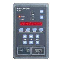
Figure 6.7 shows connections between the URTD and the MP-3000.
Use either the optical fiber or the electrical 3-wire connection. It is not
necessary to connect both. If both are connected, the MP-3000 will
use data from the optical fiber. It will default to the wired connection
only if the fiber is removed or fails.
NOTE: The optical fiber is the much-preferred method of transmitting
temperature data from the URTD to the MP-3000. It is also
easier to install.
Preassembled plastic optical fibers with connectors can be ordered
from Cutler-Hammer, or from any distributor of Agilent Technologies®
optical fiber products:
In addition, these same distributors offer long rolls of cable with
connectors which can be installed in the field. Some distributors will
make custom lengths to order.
The fiber terminations simply snap into or out of the connectors of the
URTD and MP-3000.
When using three-wire shielded cable, wire according to the connec-
tion guidelines in Table III of the Universal RTD Module IL 17367. The
three-wire shielded cable should be #16 AWG or #18 AWG. Connect
the cable shield only at the MP-3000 end, at terminal 23. Insulate the
shield and do not connect at the URTD end.
CAUTION
IF THE MP-3000 IS SUPPLIED FROM 240 VAC, THE URTD COM-
MUNICATIONS COMMON TERMINAL 22 IS AT 120 VAC WITH
RESPECT TO THE SUPPLY NEUTRAL.
The maximum cable length is 150 meters (500 feet).
6.2.7 Wiring RTDs to the URTD Module
Consult URTD Module Instruction Leaflet I.L.17367.
Three URTD terminals are provided for each RTD input. Terminals 1-15
and 17-19 are inputs for up to six winding RTDs. Terminals 20 to 25
accept up to two motor bearing RTDs. Terminals 26-31 accept up to
two load bearing RTDs. Terminals 33 to 35 accept an auxiliary RTD.
The three terminals for any unused RTD input channel should be wired
together. For example, if MW5 and MW6 are unused, MW5 termi-
nals 13, 14, and 15 should be wired together; and MW6 terminals 17,
18, and 19 should be separately wired together.
See Figure 6.9 for wiring of RTDs to the URTD inputs. Use #18 AWG,
three-conductor shielded cable. Note the connection rules in the
Figure. When making connections to a two-lead RTD, connect two of
the cable conductors to one of the RTD leads as shown. Make this
connection as close to the motor as possible. Connect the third cable
conductor to the remaining RTD lead.
Connect the shield and drain wire, along with the one cable conductor,
to the middle of the three RTD input channel terminals as shown in
Figure 6.9. The RTD cable shield should be connected only at the
URTD end, and insulated at the RTD end. The RTDs themselves must
not be grounded at the motor.
Remember to set the URTD module DIP switches according to the
types of RTDs in each of the winding, motor bearing, load bearing, and
auxiliary groups. See I.L. 17367.
The fiber length should not exceed 120 meters (400 feet). For long runs
over 10 meters, be sure to use H-P extra low loss plastic fiber HBFR-
ELS or -EUS. Do not splice fiber. Maximum short-term pulling force is
50 Newtons (11 pounds).
Surplus length of a precut fiber causes no problems. Simply coil and
tie the excess fiber at a convenient point. Avoid high tie pressure.
Bending radius of the fiber should be greater than 2 inches.
Cutler-Hammer Agilent Technologies
Length Catalog Number Number
1 meter MPFO-1 HBFR-ELS001 or
HBFR-RLS001
5 meters MPFO-5 HBFR-ELS005 or
HBFR-RLS005
10 meters MPFO-10 HBFR-ELS010 or
HBFR-RLS010
25 meters MPFO-25 MPFO-25
Uncut fiber HBFR-EUS(length)
 Loading...


