Page 7-2
www.eaton.com
IB02602002E
MP-4000
Turn off ac power again. Troubleshoot the discrete input
and/or URTD wiring, if necessary.
Reinstall the power plug into J3 of the URTD.
Check the URTD conguration DIP switches, to insure they
are set for the types of RTDs actually installed in the motor
and load equipment. See URTD I.L. 17367 for specics.
Reconnect the leads disconnected from terminals 8 and 10
Turn on ac power again.
Recheck P13L7, the state of discrete input 1, if used. It
should report DI 1 ON.
Recheck P13L8, the state of discrete input 2, if used. It
should report DI 2 ON.
Turn off ac power again. Troubleshoot the discrete input
wiring.
Remove the jumpers on the remote contacts or set them to
the normal state.
Use the MP-4000 discrete input test page indications to test
the actual operation of the contacts, if possible.
7.4 Further Checking of the Relay with AC Power
Apply ac power to the relay and optional URTD.
The MP-4000 quickly initializes and displays its status, usu-
ally READY - 3, unless the relay sample has been subjected
to an unusual combination of settings and recent prior
service or testing. Usually, one or more output relays can be
heard to click as they are energized.
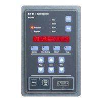
The Protection LED on the faceplate should light.
If the URTD is connected, press the Monitor mode button
and navigate to the MONT RTD page. If the MONT RTD
page cannot be accessed, the URTD module is dead or is
not communicating with the relay at all. Troubleshoot the
communications wiring or optical ber as well as the URTD
power.
Check the 11 temperature display lines. Each connected
RTD should display an appropriate value (e.g.: 25 at room
temperature). Non-functioning or unused RTD inputs display
a — character for a value.
7.5 Checking Data Communications
If the relay is equipped with a PONI, check it to conrm that
the communications network is connected.
Visit the PowerNet or other host and check the monitoring
displays for the particular MP-4000.
Conrm that the displays in view are for the correct relay.
This is easily done by disconnecting and reconnecting the
network connector.
If communications can not be established, check for address
conicts on the network (multiple devices set to the same
address) or incorrect setting of the address switches on the
PONI.
9.
10.
11.
12.
13.
14.
15.
16.
17.
18.
1.
2.
3.
4.
5.
1.
2.
3.
4.
7.6 Entering Relay Settings
Make a copy of Table 4.3 as a worksheet for recording set-
ting choices.
Read Sections 5 and 9 carefully for guidance in selecting
settings.
If desired, PowerNet or PowerPort data communications
can be used to download a pre-congured setting record to
the relay from a disk le or from a convenient worksheet on
the host display. IMPACC cannot be used to enter settings
to an MP-4000.
If electronic communications are not used, enter the settings
through the front panel in Program mode, using the Prog
button behind the security door.
After settings have been entered, exit the program mode by
pressing the Program button again.
Verify that the settings have been correctly entered using
the View SP mode button.
Reconrm that the motor nameplate values agree with the
corresponding relay settings.
Reconrm that the ratios of the phase and ground CTs in the
gear agree with the PCT and GCT settings of the relay.
CAUTION
THE MP-4000 HAS 154 SETTINGS, WHICH ARE EASY TO CON-
FUSE. DO NOT ATTEMPT TO ENTER VALUES WITHOUT USING
THE APPROPRIATE SETPOINT RECORD SHEET. IMPROPER
OPERATION AND/OR PERSONAL INJURY COULD RESULT IF
THIS PROCEDURE IS NOT FOLLOWED.
7.7 Checking Contact Outputs
DANGER
BE AWARE OF WHETHER CONTROL POWER IS APPLIED TO
THE OUTPUT CONTACTS BEFORE TESTING. AVOID UNEX-
PECTED OPERATION OF THE MOTOR CONTACTOR OR OTHER
CONTROLLED DEVICES DURING TESTING. PERSONAL INJURY
OR DAMAGE COULD RESULT.
Determine the mode of each of the output relays. Look at
settings P12L1 through P12L4.
If possible and safe, use a live test of the actual wiring or
devices operated by the MP-4000 output contacts to verify
contact operation and check wiring.
A voltmeter can be used to check energized contacts. Use
an ohmmeter or continuity checker only on dead, discon-
nected circuits.
With MP-4000 power applied, each output relay set for
Mode 1 should have its NO contact open and its NC contact
closed.
Each relay set for Mode 2 should have its NO contact
closed, and its NC contact open.
Enter the Program mode. Navigate to Page 13, SP TEST.
Settings P13L2 to P13 L5 can be used to set up each of the
output relays for test.
1.
2.
3.
4.
5.
6.
7.
8.
1.
2.
3.
4.
5.
6.

 Loading...


