Page 7-3
MP-4000 IB02602002E
www.eaton.com
Press the Reset button, as explained in Section 5, to toggle
the state of each of the relays in turn. Check the switching
of the output relay, and the energization of controlled circuits
if possible.
Exit the Program mode.
7.8 Checking the Complete Motor Drive System
DANGER
THE CONTACTOR CONTROL CIRCUIT IS TO BE RECONNECTED.
AT THIS TIME, THE MOTOR ASSOCIATED WITH THE APPLICA-
TION CAN BE STARTED. IT IS IMPORTANT TO ENSURE THAT
ALL SAFETY PRECAUTIONS ASSOCIATED WITH ROTATING
EQUIPMENT AND THE ASSOCIATED DRIVEN MECHANISM ARE
TAKEN. FAILURE TO DO SO CAN RESULT IN SERIOUS OR FATAL
INJURY AND/OR EQUIPMENT DAMAGE.
Disconnect all ac power from the system.
Reconnect the contactor lead to MP-4000 trip relay terminal
12.
Check all rotating components and driven mechanisms as-
sociated with the motor for secure connections.
Clear away any loose or foreign objects.
Clear all personnel from the area of the motor and driven
mechanisms.
Turn on all ac power.
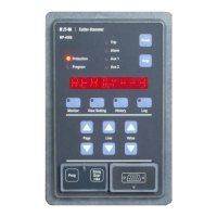
Make sure the MP-4000 Protection LED is on, and that the
display reads READY - 3.
Follow any startup procedures for the load equipment.
Start the motor using the external start switch or contacts.
Using the information supplied by the application engineer
or equipment manufacturer, verify that the motor is operating
properly.
7.
8.
1.
2.
3.
4.
5.
6.
7.
8.
9.
10.
With the motor running, use a clamp-on type ammeter to
measure the ac current on each of the motor phases.
Verify that the I
A,
I
B,
and I
C
currents, as indicated by the MP-
4000 on the MONT I Page of the Monitor mode are within
approximately 5% of the ammeter values.
If the current during this test is well below FLA, or if the CTs
are far from the optimum ratio, errors may be larger. This
test is intended to show incorrectly set CT ratios or faulty wir-
ing, rather than the precision of measurements.
If a ground CT is connected, check ground current IG. In-
vestigate the cause of any abnormal ground leakage current
ow.
Using a voltmeter, verify VA, VB, VC, as indicated by the
MP-4000 on the MONT V page of the monitor mode are
within 5% of the voltmeter value.
Check the percent unbalance display %UB for consistency
with the ammeter measurements, given the acceptable error
ranges.
When the reverse setpoint is set, this is indicated by a nega-
tive sign preceding the unbalance display and the MP-4000
relay does not trip when sensing an ACB phase rotation, but
trips when sensing an ABC phase rotation.
If the analog transducer output is connected, determine
which measurement it is transmitting - view Setting P11L1.
Check that the analog output current corresponds to the
displayed value of the selected parameter.
If a PowerNet data communications host is connected,
upload the starting current prole and check for coordination
with cold-start protection curves on the PowerNet display.
It is wise to verify the ability of the MP-4000 to open the
contactor and trip the motor. The easiest way is by remote
trip, via remote trip contact or data communications. Many
other internal functions can be manipulated to force a relay
trip. One technique is to connect a shorting jumper across
the relay current terminals for one of the three phases. This
short should produce an unbalance trip, or a thermal trip
after some time.
11.
12.
13.
•
•
•
•
•
•
•
•

 Loading...


