Instruction Leaflet IL0102002E
Effective April 2018
Ring Main Unit Operation Instruction
10 EATON CORPORATION www.eaton.com
Figure 6-2 Basic schemes
7.1. Overall structure
The typical scheme is a one/in-two/out three-section common
enclosure RMU, including one incoming, one ring feeder and one
ring outgoing.
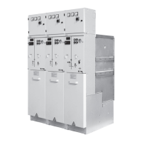
The layout of the typical scheme is shown in Figure 4 (RVAC-KKT).
The overall structure is composed of two major parts, the
gas-filled sealed housing part and the non-gas-filled part such as
the control compartment, cable compartment, frame, and
pressure relief channel. The high voltage circuit is within the
gas-filled sealed housing, and the mechanism compartment is on
the top front, while the pressure relief channel is on the bottom
front. Fully shielding cable terminals are used for incoming and
outgoing lines.
7.2.1. Sealed housing
7.2. Component structure
The sealed enclosure housing is made of high-quality stainless
steel plates, using fully enclosed welding method and SF6 gas,
with the rated pressure of 0.03 MPa. During the whole running
life, safe operations can be maintained without the need to refill
the gas. After assembling, the gas-filled housing can not be drilled
nor welded.
7.2.2. Three-position Load switch
The three-position load switch is installed inside the gas-filled
housing, with its operating mechanism installed inside the control
compartment. The three-position load switch offers closing,
opening and grounding positions. The three-position load switch is
in the opening position when the knife is in the middle position.
The three-position load switch is in the closing position and ground
position separately when the knife is in the two-limit positions.
The load switch side and the ground switch side of the
three-position load switch are equipped with clear and reliable
mechanical opening/closing indicator (see Figure 7).
 Loading...
