Instruction Leaflet IL0102002E
Effective April 2018
Ring Main Unit Operation Instruction
11EATON CORPORATION www.eaton.com
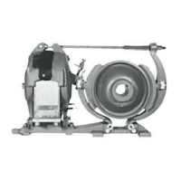
Closing position Opening position Grounding position
Figure 7 3-position opening/closing position indication
7.2.3. Fuse ground switch
The combination unit branch circuit (load switch + current limiting
fuse) is equipped with a fuse ground switch for linkage operations
with the three-position load switch, offering reliable grounding to
the fuse outgoing side. When the load switch is in closing/opening
operation, the fuse ground switch basically remains non-operating.
When the three-position load switch is in ground position, the fuse
ground switch makes reliable contact with the fixed contact base
at the fuse outgoing side, to ensure the fuse outgoing side is
reliably grounded.
7.2.4. Fuse
The fuse and the load switch constitute the transformer protection
circuit. Highly quickbreak current-limiting fuse is installed inside
the epoxy casting insulation housing. In the case of a short circuit,
after the fuse is blown out, the striker will be ejected to open the
load switch, enabling the fault line to be removed.
7.2.5. Frame
The frame (the housing except the sealing enclosure) is the basic
body of all the parts and components, to support and secure the
sealing enclosure. The frame uses aluminum- zinc plates formed
with multiple bendings, to be connected with high strength bolts,
nuts (Level 8.8) and rivets. The frame can be divided into three
main compartments: the control compartment, cable
compartment and pressure relief channel. There are a mechanism,
a fuse holder and a secondary circuit inside the control
compartment. The cable compartment contains a cable, its holder,
and the ground bus bar, with optional current transformer as
needed. The pressure relief channel is located behind the cable
compartment. On the front is located a pressure meter, a main
wiring mimic diagram, a voltage presence display, an operating
hole and operation buttons, a nameplate, a mechanism
compartment door, and a cable compartment door.
7.2.6. Mechanisms and their mechanical interlock
The three-position load switch is equipped with a spring operating
mechanism, offering reliable mechanical interlocking. The load
switch must be operated on according to specified operating
procedures.
Interlocking conditions are as follows:
Only when the load switch is moved to the opening position,
the ground switch can be closed;
Only when the ground switch is moved to the opening position,
the load switch can be closed;
Only when the ground switch is moved to the ground position,
the cable compartment door can be opened;
Only after the cable compartment door is closed, the ground
switch can be opened.
a.
b.
c.
d.

 Loading...