10
EN
15. SUPPLIED TECHNICAL DOCUMENTATION
15.1 STANDARD VOLTAGES SHOWN ON THE PLATE WITH THEIR RE-
SPECTIVE TOLERANCES
15.2 MOTOR OUTPUT REDUCTION FACTORS
When the motor-driven pump is installed in a site where the ambient tem-
perature is higher than 40°C and/or its altitude is over 1000 m above sea
level, the motor’s output decreases.
The table attached features the reduction factors based on temperature
and altitude. To prevent overheating, you must replace the motor with a
different version whose rated output multiplied by the factor corresponding
to the temperature and altitude is greater than or equal to that of the stand-
ard motor.
The standard motor can only be used if the relevant application can accept
a reduction in ow rate, achieved by throttling the delivery line so as to re-
duce the current absorbed by an amount equal to the correction factor.
T(°C)
Altitude (m.a.s.l.)
1000 1500 2000 2500
40 1 0.96 0.94 0.90
45 0.95 0.92 0.90 0.88
50 0.92 0.90 0.87 0.85
55 0.88 0.85 0.83 0.81
60 0.83 0.82 0.80 0.77
65 0.79 0.76 0.74 0.72
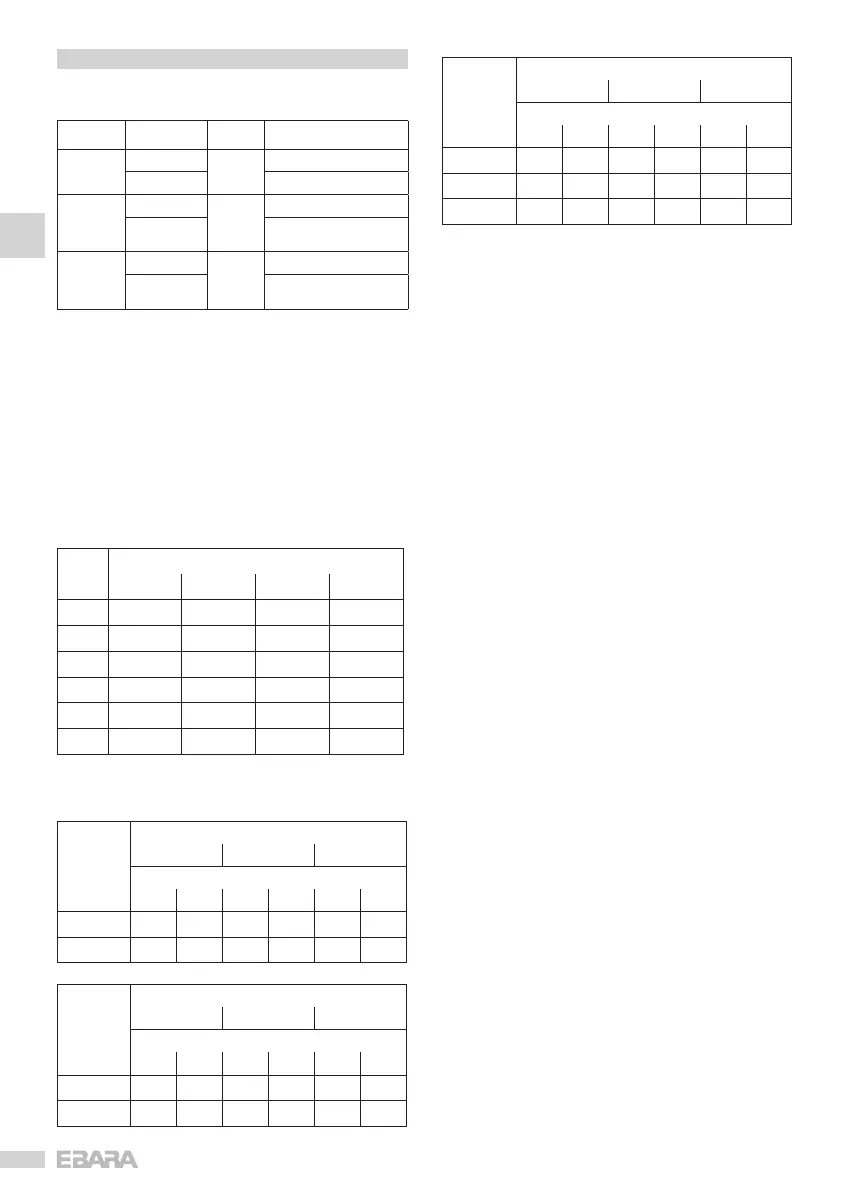
15.3 MAXIMUM WORKING PRESSURE CHART
Maximum
working
pressure
Pump model
EVMS1 EVMS3 EVMS5
Hz
50 60 50 60 50 60
1.6
2-26 2-18 2-21 2-15 2-17 2-12
2.5
27-39 20-29 23-33 16-23 19-27 13-19
Maximum
working
pressure
Pump model
EVMS10 EVMS15 EVMS20
Hz
50 60 50 60 50 60
1.6
2-15 1-10 1-11 1-7 1-9 1-7
2.5
16-23 11-16 12-17 8-12 10-16 8-10
Maximum
working
pressure
Pump model
EVM32 EVM45 EVM64
Hz
50 60 50 60 50 60
1.6
1-7 1-5 1-3 1-4 1-6 1-4
2.5
8-12 6-8 4-9 5-6 6-7 –
3.0
13-14 8-10 10 – – –
15.4 AVOIDING CAVITATION
Cavitation, as you may know, is a destructive problem for pumps, a phe-
nomenon that is encountered when the water drawn in is transformed into
steam inside the pump. EVM pumps, tted with internal hydraulic parts
made from stainless steel, suffer less than other pumps built with materials
of poorer quality, though they are not entirely immune to the damage that
cavitation brings.
Hence pumps must be installed in compliance with the laws of physics and
with rules relating to uids as well as to the actual pumps.
Below we give you just the practical results of the above-mentioned rules
and laws of physics.
Under standard environmental conditions (15°C, at sea level), water turns
into steam when subjected to a negative pressure greater than 10.33 m.
Hence 10.33 m is the water’s maximum theoretical suction height. EVM
pumps, like all centrifugal pumps, cannot exploit theoretical suction height
to the full owing to their internal loss, known as NPSHr, which has to be
deducted. Hence the theoretical suction lift of each EVM pump is 10.33 m
less its NPSHr at the work point in question.
The NPSHr can be determined by consulting the standard curves featured
in the brochures and must be taken into consideration when rst selecting
the pump.
When the pump is part of a ooded installation or has to draw cold water
from 1 or 2 m with a short pipe with one or more wide bends, NPSHr can
be disregarded. Consequently, the more difcult the installation, the more
the NPSHr value has to be taken into consideration. Installation becomes
difcult when:
a) Suction height is high;
b) Suction line is long and/or has lots of bends and/or has several valves
(high pressure losses along suction line);
c) Foot valve has high ow resistance (high pressure losses along suction
line);
d) Pump is used with a ow rate close to the maximum rated ow rate
(NPSHr increases as ow rate increases over the rate where efciency
is highest);
e) Water temperature is high. (It is likely you will have to install the pump
with a ooded arrangement where values approach 80-85°C);
f) Altitude is high (in the mountains).
[kW] Frequency [Hz] Phase [~] UN [V] ± %
≤ 0.55
50
1 ~
230 ± 10%
60 220 ± 10%
0.37 ÷ 4.0
50
3 ~
230 Δ / 400 Y ± 10%
60
220 Δ / 380 Y - 5% /+ 10%
460 Y ± 10%
≥ 5.5
50
3 ~
400 Δ / 690 Y ± 10%
60
380 Δ - 5% /+ 10%
460 Δ ± 10%


 To Next Page
 Loading...