17
2.4.7 Colorimetric Reaction Cell
The colorimetric reaction cell is made of glass with a diameter of 16 or
26 mm, depending on the measured parameter. The cell is located
inside a thermostatic block. You can easily slide out the cell by first
taking off the tubing around the cell, twist then pulling the cell straight
up. The 16 mm cell comes with two halves of a black sleeve adapter
held together with an O-ring.
IMPORTANT: The sleeve adapter is made with apertures to focus the light path through the cell. Make
sure that the light pathway is aligned with these apertures for the unit to work properly. This can be
done by twisting the sleeve and aligning its creases with a small white dot on the top of the heater
block. When the pathway is aligned correctly, the display READING will be greater than 0. We have
added additional white dots on the sleeve adapter and on the top of the heater block so that it is easier
to align.
2.4.8 Sample Drain
Tubing for the sample drain maintains a constant level of few cm of liquid in the colorimetric cell.
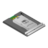
2.4.9 Electronic Components
The microprocessor based controller and its PCB assembly are located in the electronic section. The
cover and touch screen interface have been removed to show the internal construction. The controller
handles all analyzer operations. It collects all the information and data coming from the different
analyzer devices and controls all I/O dialogue with the user touch screen interface and data transfer
equipment. Remove the cover to adjust the REFERENCE LED voltage. This adjustment should only be
made when a CLEAN reaction cell filled with deionized water reads below 8. Turn the potentiometer
clockwise to increase the REFERENCE value to 9.00 ± 05.