23
4.5.2 AC Power Connections
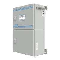
The CA-6 Analyzer is designed for operation with 110-220Vac, 50-60 Hz power. The supplied AC power
cord exits through a port on the top side of the electrical compartment. All the connections must be
made in accordance with national or local regulations. The analyzer is equipped with an internal power
switch (main power switch). It is recommended that the CA-6 analyzer is connected to power via a
circuit breaker or an ON/OFF switch installed near the unit.
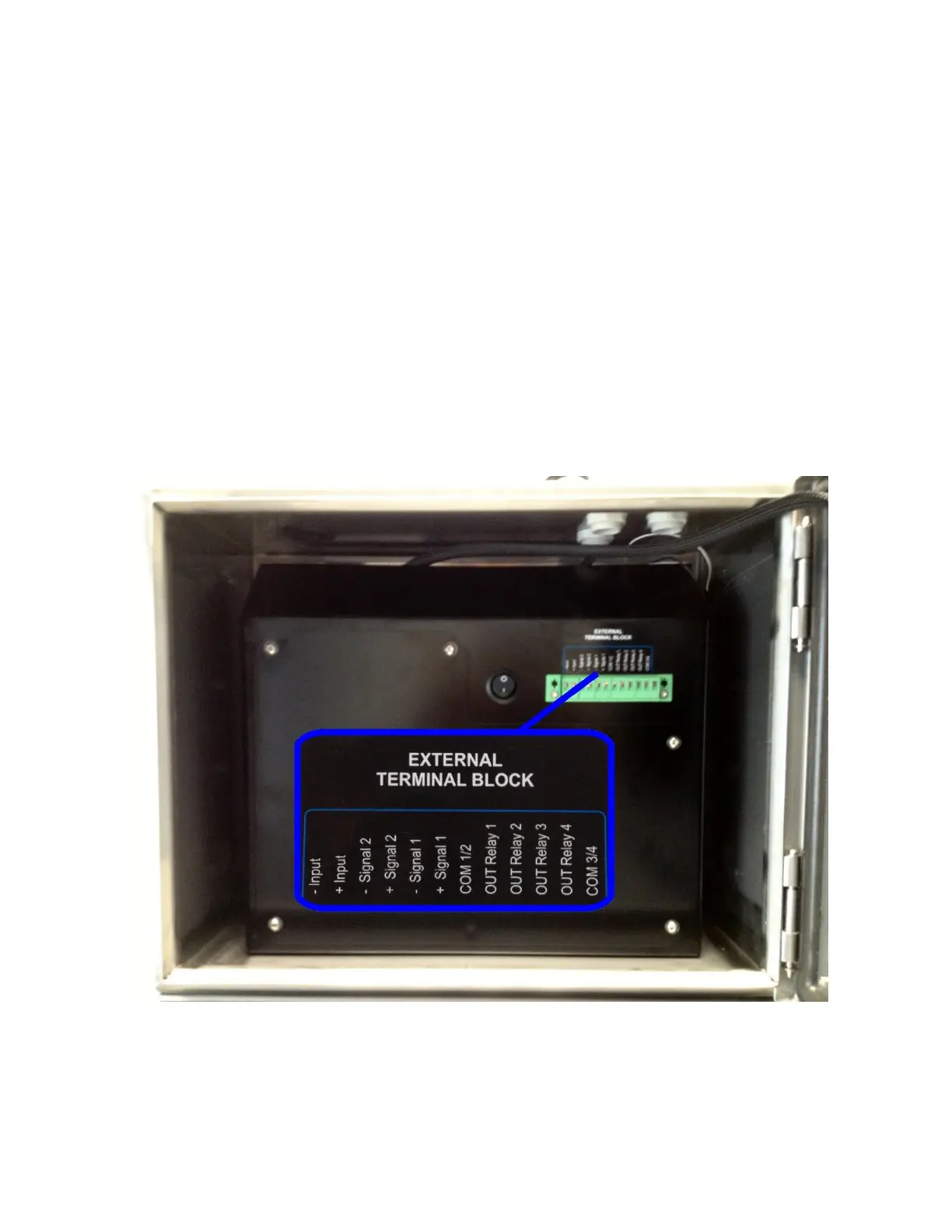
4.5.3 Signal Output Connections – TB (4-20 mA, alarm, aux, Modbus TCP/IP, Modbus RS485)
A digital input (- Input + Input) for remote start and stop. This function gives the possibility to
remotely operate the process analyzer, i.e. START and STOP running.
(1) 4-20 mA output (-signal 1 / + signal 1) the second 4-20 mA output (-I signal 2 + I signal 2) is
available only for dual channels analyzers, optional for single channel analyzers.
(4) configurable relays (Normally Open Relays)