24
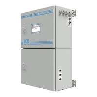
Modbus TCP/IP Data. Connect the Analyzer to a physical network by plugging a network cable
into the RJ45 jack located on the top of the enclosure. Default configuration is DHCP ON and
may be changed using the analyzer configuration menus. Access the ADMIN account and select
SERVICE. Located at the top-right of the screen, just to the left of the window close “X” is a
hidden button. Pressing this enables access to the Ethernet configuration menu. Enter the
static IP address and network configuration data <or> read IP address obtained via DHCP. From
another network device use the PING command to verify connection to the DHCP address or
static IP. If PING indicates data loss, swap the network cable for a cross-over style and retry.
Once PING indicates a valid physical connection data may be accessed and formatted using the
table below.
RJ45 located on the top enclosure
DCHP (default) or Static IP
Format (little-endian byte swap)