18
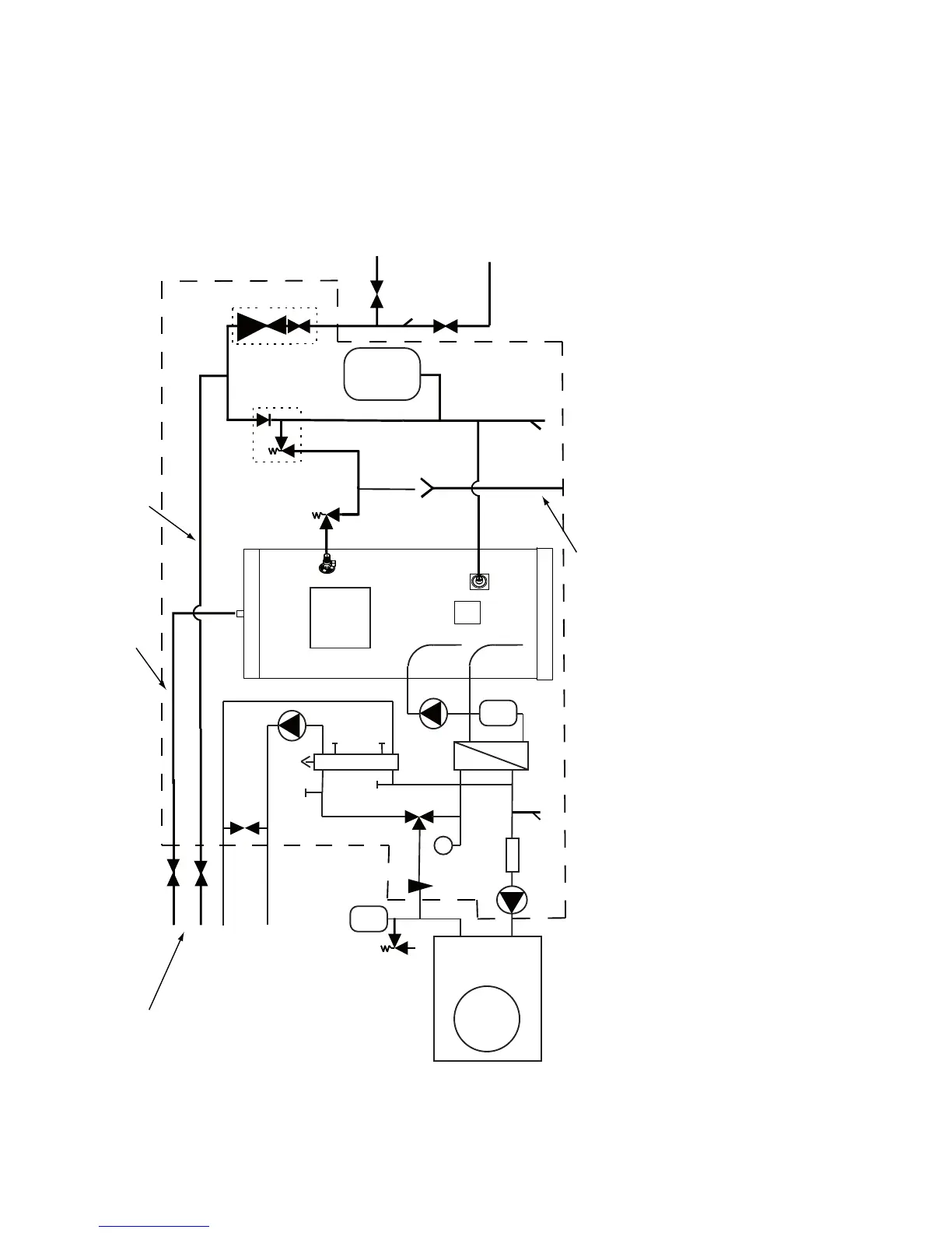
Fig 7 - Schematic installation diagram
Balanced cold water
draw-off
MCWS to Kitchen
(unbalanced cold
mains supply)
Incoming Cold
Water Main
Discharge pipe to atmosphere
(see page 12 “Installation - Discharge”)
HWS supply
Balanced HWS and
MCWS to bathrooms,
showers, cloakrooms,
etc
Pa
To space heating
circuit Zone 1
1
2
3
4
5
6
7
8
9
10
11
12
13
14
15
16
17
18
19
20
21
22
23
26
25
24
27
Parts shown within dashed
line are supplied
KEY
1 Heat Pump 13 Scale Trap 25 Primary circuit draw off point
2 Cylinder 14 DHW Circulating Pump 26 Automatic Air Vent
3 FTC5 Controller 15 Flow Sensor 27 Differential Pressure Bypass Valve
4 Immersion heater 16 Primary Pump (supplied loose
5 3.5 bar Pressure reducing Valve incorporating 17 Primary Expansion Vessel
Strainer and Check Valve (supplied loose) 18 Primary Pressure Relief valve
6 8 bar Expansion Valve and Check Valve 19 Magnetic Filter
7 DHW Expansion Vessel (supplied loose) 20 Primary System Pressure Gauge
8 Stop Cock 21 3 Way Motorised Diverter Valve
9 Mains Stop Cock 22 Low Loss Header incorporating ports for
10 Tundish 2nd heating zone and alternative heat source
11 Temperature/Pressure relief Valve 23 Primary Pump
12 Plate to PLate Heat Exchanger 24 DHW Drainoff point