4
GENERAL REQUIREMENTS
IMPORTANT: THIS APPLIANCE CAN BE USED BY CHILDREN AGED FROM 8 YEARS AND ABOVE AND PERSONS WITH
REDUCED PHYSICAL SENSORY OR MENTAL CAPABILITIES OR LACK OF EXPERIENCE AND KNOWLEDGE IF THEY
HAVE BEEN GIVEN SUPERVISORY OR INSTRUCTION CONCERNING USE OF THE APPLIANCE IN A SAFE WAY AND
UNDERSTAND THE HAZARDS INVOLVED. CHILDREN SHALL NOT PLAY WITH THE APPLIANCE. CLEANING AND
USER MAINTENANCE SHALL NOT BE MADE BY CHILDREN WITHOUT SUPERVISION.
WARNING: Do not switch on if there is a possibility that the water in the heater is frozen.
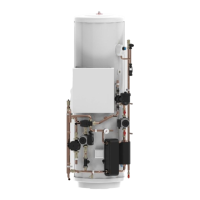
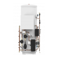
COMPONENT CHECK LIST
Before commencing installation check that all the components for your Air Source Heat Pump cylinder are contained in the
package. The following components are supplied with your unit :
• Factory tted
Temperature and Pressure Relief Valve (set at 90°C/10bar)
Immersion heater and over-temperature cut-out
Expansion core unit (comprises expansion valve and check valve)
Tundish
Primary circulating pump (Low Loss Header to Heat Pump return) - Grundfos UPM GEO (150/170/210 litre models),
Grundfos UPMXL GEO (250/300 litre models)
Primary circulating pump (Low Loss Header to Heating circuit) - Grundfos UPM3 AUTO L (all models)
DHW circulating pump
3 Way motorised diverter valve
Primary to DHW plate to plate heat exchanger
Fernox TF1 Compact Magnetic lter
Primary circuit lling loop
Primary circuit pressure gauge
Automatic air vent
FTC5 Controller
Solar over-temperature thermal cutout (Solar models only)
• Supplied loose
Mitsubishi Electric CH/DHW Main Controller
Potable water expansion vessel
Cold water combination valve (comprises pressure reducing valve, strainer, check valve)
STORAGE AND HANDLING
Prior to installation the Pre-plumbed cylinder unit must be stored vertically upright on a secure, level surface in a dry, frost free
environment. Take note of the weight of the product and follow safe working practices when lifting, moving or manipulating
into position. DO NOT lift by the pre-plumbed pipework manifold.
SITING THE UNIT
The Pre-plumbed cylinder unit must be vertically oor mounted. It can be placed anywhere convenient provided the discharge
pipe(s) from its safety valves can be correctly installed and all pre-tted ancillary parts can be accessed for servicing and/or
maintenance. Areas that are subject to freezing must be avoided. Ensure that the oor is of sufcient strength to support the
“full” weight of the unit (Table 1, page 5). Pipe runs should be kept as short as possible for maximum economy.
Additional automatic air vents (AAV) (not supplied) may be required at high points in the primary system where pipework is
located above the level of the cylinder.
WATER SUPPLY
Bear in mind that the water supply to the property will be supplying both the hot and cold water requirements simultaneously.
It is recommended that the maximum water demand is assessed and the water supply checked to ensure this demand can
be satisfactorily met.
NOTE: A high water pressure will not always guarantee high ow rates.
Wherever possible the cylinder supply pipe should be 22mm. We suggest the minimum supply requirements should be 1.5
bar pressure and 20 litres per minute ow rate. However, at these values outlet ow rates may be poor if several outlets are
used simultaneously. The higher the available pressure and ow rate the better the system performance.
The cylinder has an operating pressure of 3.5 bar which is controlled by the cold water combination valve assembly. The cold
water combination valve assembly can be connected to a maximum inlet pressure of 16 bar.