11
www.ecoflam-burners.com
EN
420010371905
Installation
- Burner assembly
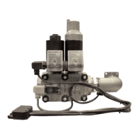
Oil connection
The filter must be located in such a way
that the correct hose routing cannot be
impaired. The hoses must not kink.
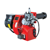
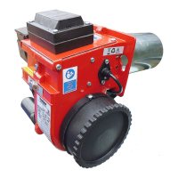
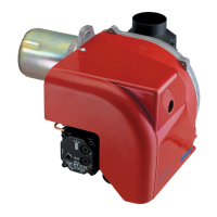
Burner assembly
The burner is fixed by mean of connecting
flange and therefore to the boiler.
Installation:
• To fix the flange 3 to the boiler with
the screws 4.
• Turn the burner slightly, guide it into
the flange and secure using screw 5.
Removal:
• Loosen screw 5.
• Turn the burner out and pull it out of
the flange.
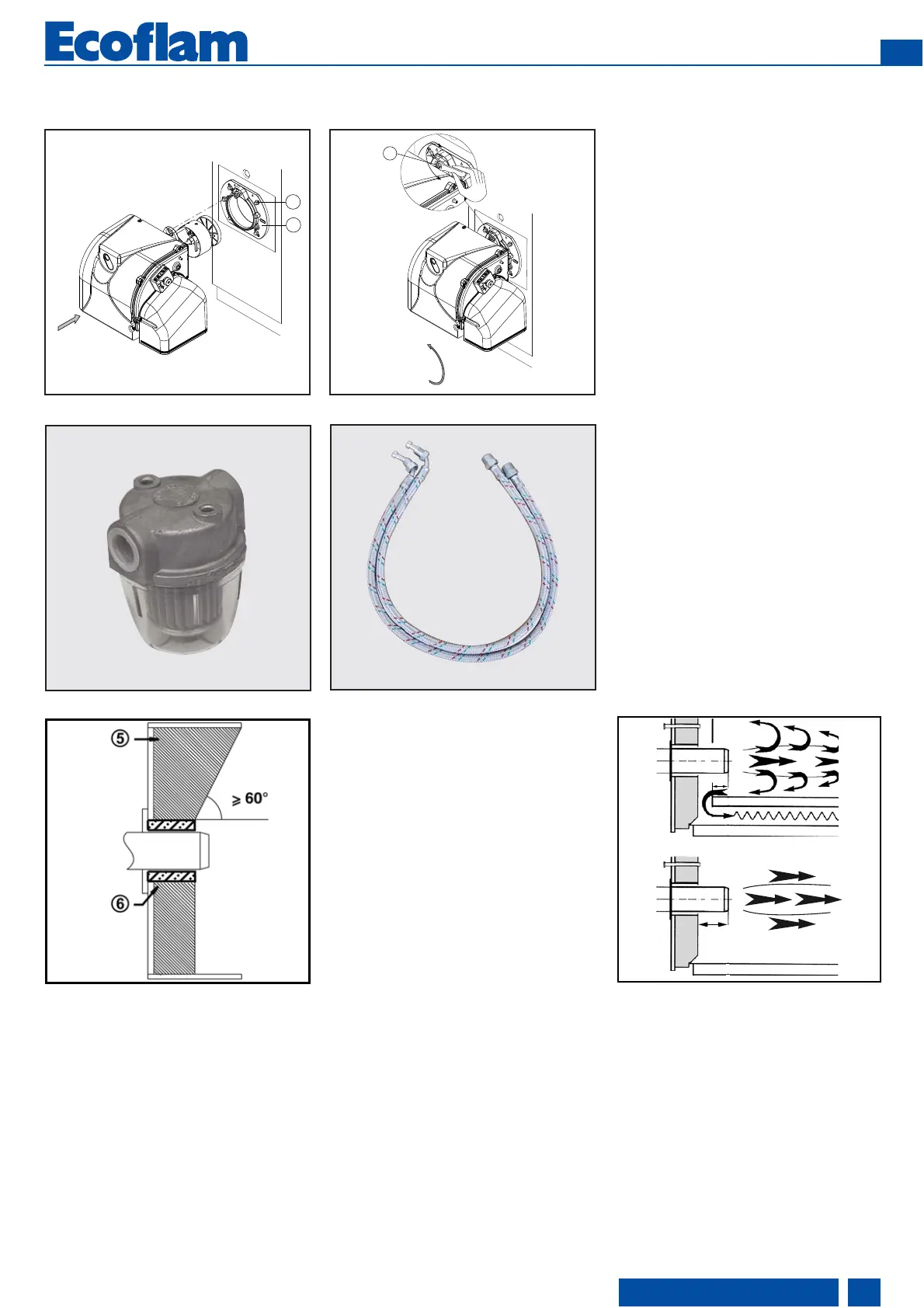
Burner pipe insertion depth and
brickwork
Unless otherwise specified by the boiler
manufacturer, heat generators without a
cooled front wall require brickwork or
insulation 5 as shown in the illustration.
The brickwork must not protrude beyond
the leading edge of the flame tube, and
should have a maximum conical angle of
60°. Gap 6 must be filled with an elastic,
non-combustible insulation material. For
boilers with reverse firing, the minimum
burner tube insertion depth A as
specified in the boiler manufacturer’s
instructions must be observed.
On boilers the blast tube insertion depth
should be observed as per the boiler
manufacturer's instructions.
Reverse flame boiler :
A = 50-100 mm.
Three pass boilers :
A1 = 50-100 mm.
Exhaust system
To avoid unfavourable noise emissions,
right-angled connectors should not be
used on the flue gas side of the boiler.