Part 7 - Central heating (CH) and Domestic Hot Water (DHW) circuit
Warning
If no diffusion-tight pipes for supply and return (CH circuit) are applied for radiators or floor heating, place a
partition between the CH water of the boiler and the water in the system. E.g. use a plate heat exchanger. A
plate heat exchanger prevents contamination of the heat exchanger by, among others, magnetite. When such a
partition is not placed, the guarantee for all parts in the supply and return of the unit will be null and void.
The appliance has been equipped with a drain valve allowing simple draining of the water. The appliance has a
pressure relief valve that needs to be installed directly outside the boiler in the return pipe. The pump vent has
been connected through the overflow valve connection making visible any leakage from the vent on the outside of
the appliance. The appliance also has an internal adjustable by-pass to achieve circulation. If necessary, place
an external by-pass a minimum of 6 meters (20') away from the boiler. Flush the system with clean tap water
before the first start-up to prevent contamination of the heat exchanger of the CH boiler.
Frost protection
The unit has a built-in frost protection system that starts up the CH pump and the burner in case the boiler
water temperature drops below 6 °C (43 °F).
Prevent corrosion
To prevent the CH system from corroding, pay attention to the following: Only use pure filling water (no
additives). The pH-value must be neutral (7 – 8.5). If not, contact the supplier. Thoroughly flush the CH system
before putting it into operation. Any synthetic pipes used must be oxygen diffusion tight. If not, place a partition
(e.g. a heat exchanger) between the boiler circuit and the circuit with the plastic pipes. Check for leaks in the
circuit to prevent oxygen penetrating.
Vent
Vent the system after filling and before putting the system into operation (section 10).
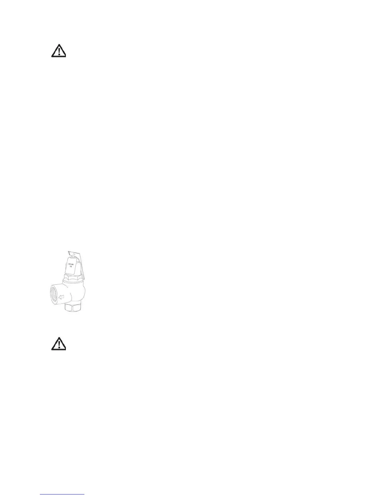
Pressure relief valve
The appliance has a pressure relief valve (figure 7.1) that needs to be installed directly outside the boiler in the
return pipe (A, figure 7.2) and, if installed, downstream of the external expansion tank. Connect discharge
piping to a safe disposal location.
Figure 7.1 PR Valve
Warning
To avoid water damage or scalding due to relief valve operation, take the following into account when
installing the valve:
Discharge line must be connected to relief valve outlet and run to a safe place of disposal. Terminate
the discharge line in a manner that will prevent possibility of severe burns or property damage in case
the valve discharges.
Provide piping that is the same size as the safety relief valve outlet.
Discharge line must pitch downward from the valve and terminate at least 152 mm (6”) above the
floor drain where any discharge will be clearly visible.
The discharge line shall terminate plain, not threaded, with a material serviceable for temperatures
of 190 °C (375 °F) or greater.
Do not pipe the discharge to any place where freezing could
occur. Do not plug or place any obstruction in the discharge line.
Never block the outlet of the safety relief valve.
Failure to comply with the above guidelines could result in failure of the relief valve to operate,
resulting in possibility of severe personal injury, death or substantial property damage.
39