Part 7 - Central heating (CH) and Domestic Hot Water (DHW) circuit
Legend
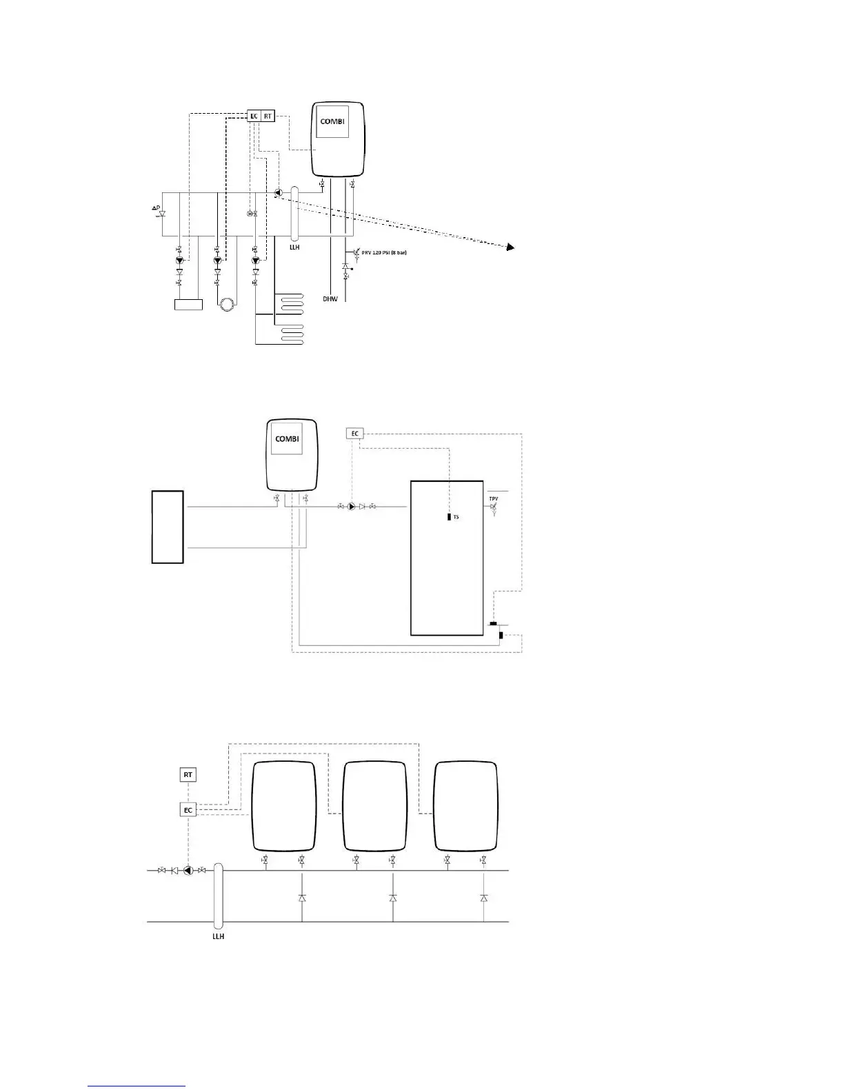
For boiler details refer to layout no. 2.
Combi Combi appliance
PRV Pressure Relief Valve
DHW Domestic Hot Water
LLH Low Loss Header
EC External control
RT Room Thermostat
Pump and LLH only required if pressure loss
in served system is too high.
Cold water in
9) System layout: Combi appliance with:
Multiple CH systems (radiators, air handler, floor heating)
For boiler details refer to layout no. 2.
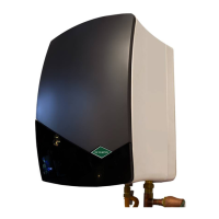
Temperature Pressure Relief Valve
Heating circuit
10) System layout: Combi appliance with:
Heating circuit
Connected tank via the boiler’s internal DHW plate heat exchanger
Legend
For boiler details refer to layout no. 1 and 2.
LLH Low Loss Header
EC External control (cascade control)
RT Room Thermostat
11) System layout: Combi or Heating only appliance in cascade configuration
with: Heating circuit with low loss header
46