3 Setup
3.1
General setup
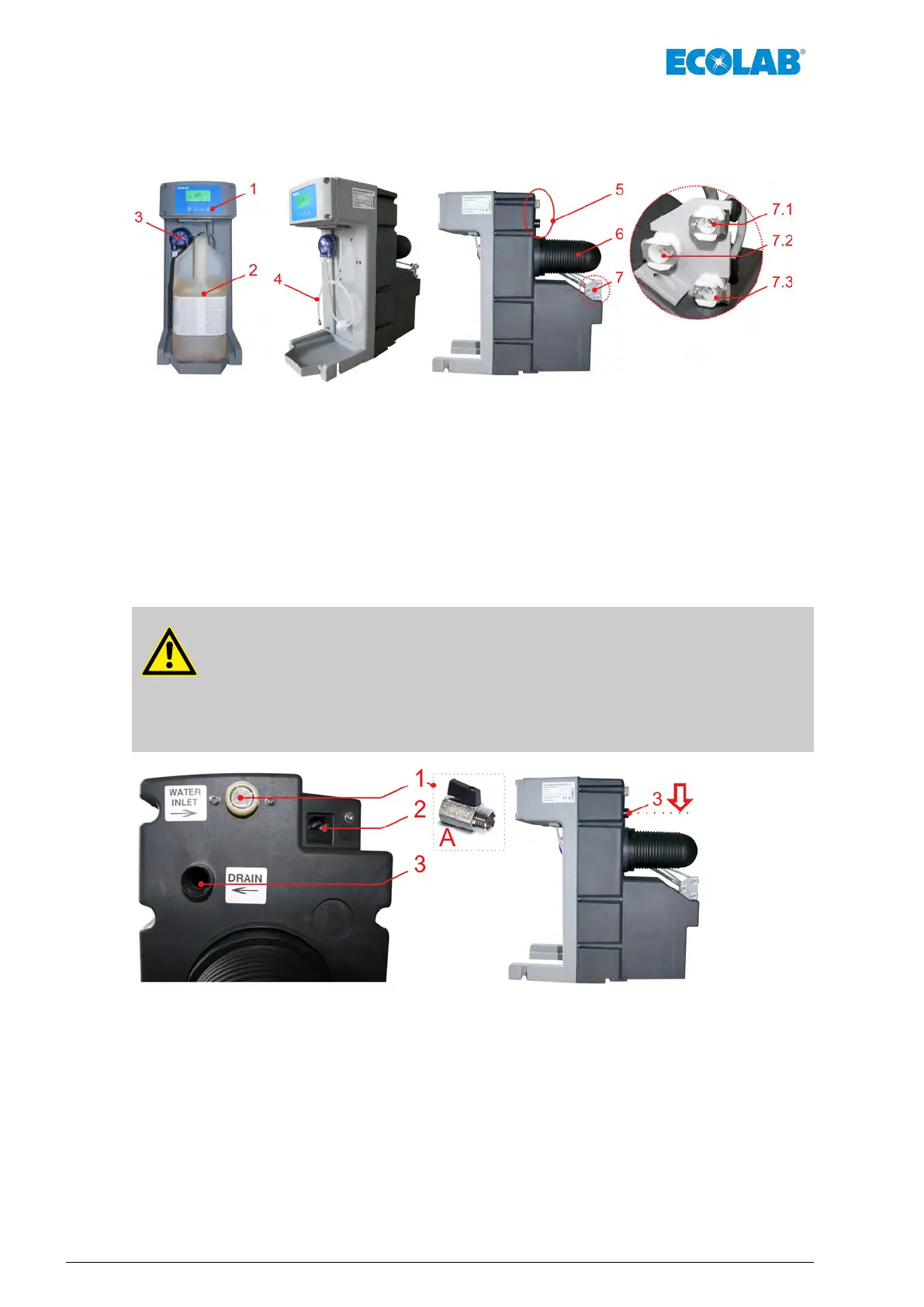
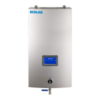
Fig. 1: Setup
1 Operator panel
2 Canister with detergent
3 Peristaltic pump (p-pump)
4 Suction hose
5 Water inlet
6 Pressure vessel
7 Coupling to (Keg) module
7.1 Continuous air
7.2 Outlet for the medium (cleaning and rinsing process)
7.3 Control air
3.2 Detailed look at the water and electrical connections
CAUTION!
– You have to install a ball valve upstream of the ‘W
ATER INLET’ (pos. 1).
– This valve must be closed in ‘BEVERAGE mode’!
– The ‘DRAIN’ overflow (pos. 3) must be connected to the drain.
– The drain pipe must run under the ‘DRAIN’ connection (pos. 3).
Fig. 2: Water and electrical connections
1 Water supply, Pressure: max. 0,8 MPa (8 bar), Flow rate: max. 3 l/min
2 Connection socket for power supply
3 Overflow, DN15, Flow rate: max. 4 l/min
A Ball valve (art. no. 415502019) with flat sealing (art. no. 417000288)
Setup
18Rev. 04-06.2018