This manual is the intellectual property of Ecoso. Copying and reprinng is prohibited. © 2021
8
INSTRUCTION MANUAL ECOSOFT RO SYSTEM
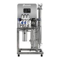
MO6500BWTSS
3.9 Let the unit run for 1 hour discarding both permeate and concentrate to drain to ush out
the membrane preservave. Watch ow rate and pressure gauges to make sure they do not deviate
from the setpoint.
Take care not to exceed the maximum specied pressure in membrane module. If the
membrane pressure rises above the upper limit in specicaon, open recycle ow
regulang valve to bring it down.
Turn regulang valve knobs smoothly when regulang recycle and drain ow. Do not
make rapid turns or apply disproporonate force as this can damage the unit.
START UP THE SYSTEM AS FOLLOWS:
3.7 Fully open recycle and drain ow regulang valves before powering up the system. Make
sure to discard all permeate obtained during the rst run of the RO system.
3.8 Power up the system. The controller will boot up and begin service. Wait unl the air
is vented from the system and the pressure reading stabilizes. In case low feed pressure fault or
another fault occurs, see Troubleshoong secon for help.
Tighten drain ow control valve unl drain rotameter reading meets the specicaons (see
Table 1). Then, start turning down recycle regulang valve. This will rapidly raise pressure in the
membrane array (shown on pressure gauge up front). Stop regulang recycle ow control when the
permeate ow rate reaches full capacity or when the pressure in the membrane module reaches
the upper limit (see Table 1).
Aer seng up the recycle ow rate, check the drain ow rate again and readjust it to the
approximate value obtained with the following formula:
EXAMPLE:
Assume feed water TDS = 6 g/l, t = 15 °C.
On Figure 2.1 MO6500BWTSS ow capacity chart the following approx. values will be found:
Permeate ow rate = 300 l/h ≈ 5 l/min
Recovery ≈ 55% = 0.55
Using the above formula, Target Drain Flow Rate = 300/0.55 - 300 = 245 l/h ≈ 4 l/min
Therefore, the RO system has to be set up as follows:
1. Tighten Drain Flow Control unl Drain rotameter shows 4 LPM.
2. Tighten Recycle Flow Control unl Permeate rotameter shows 5 LPM.
3. Recycle rotameter ow rate depends on other factors and may vary signicantly, but should in most
cases be within the range specied in Table 1.
4. Verify that the Operang pressure does not exceed the maximum value of 25 bar.
5. Verify that the obtained Permeate Flow Rate and Drain Flow Rate are consistent with the Permeate
Recovery used in the calculaon.
Target Drain Flow Rate =
Permeate Flow Rate
- Permeate Flow Rate
Permeate Recovery
where the Permeate Flow Rate and Permeate Recovery values are to be found on the system
capacity graphs (from your raw water TDS and temperature) in Product descripon secon.