This manual is the intellectual property of Ecoso. Copying and reprinng is prohibited. © 2021
7
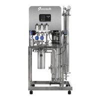
INSTRUCTION MANUAL ECOSOFT RO SYSTEM
MO6500BWTSS
3. INSTALLATION AND STARTUP
3.1 Rest the unit on a at level surface capable of supporng its weight (see Table 1). Install
permeate tank next to the unit. Inspect the RO system carefully for damage, including piping, valves
and instruments, pump, pressure vessels, prelter housings, electrical panel before proceeding
with connecon and startup.
3.2 Install membrane in each pressure vessel as follows. Remove the pipes connected to the
pressure vessel ends. Take apart clamp unions or dismantle ange/Victaulic couplings if necessary.
Aer all adjacent pipes are disconnected and will not get in the way, remove one of the lids of each
pressure vessel. Typically, the lids are held with clamps that must be loosened.
Make a cut in membrane packaging bag and insert membrane in the pressure vessel. The brine
seal ring has to be at the feed end of the vessel. Central tube of the membrane has to mate with
membrane adapter installed at the concentrate end of pressure vessel. If necessary, remove the
opposite lid also for easier inseron of the membrane. Install the lids back in place. Install the
holding clamps back on the lids.
3.3 Connect raw water pipeline from the water main or booster pump. Connect drain and
permeate pipes to the respecve connecon ports of the RO system. Recommended pipe size is at
least equal to that of the connecon port. Use appropriate ngs as necessary. Ensure air gap at
the end of drain line to prevent backsiphonage. Run permeate pipe from the permeate outlet to
the permeate tank and connect using appropriate ngs or glands.
3.4 Put the oat switch inside permeate tank aer moving ballast the necessary length up
the cord to provide enough level dierence between acvated and deacvated posion. Aer the
rst lling of the tank, verify that the oat switch acvates and deacvates in the right posions.
3.5 If the RO system has permeate rinse enabled, install the necessary piping. If using
service interrupon by external signal (microswitch), remove jumper from the stop terminals in
the electrical panel. Then, run a cable from the microswitch to the panel and connect to the Stop
terminals. If using anscalant or other RO chemicals, refer to the dosing pump’s instrucon manual
for informaon concerning the dosing pump.
3.6 Run power to the RO system. Connect the phase(s), neutral, and earth conductors as
shown on the electrical diagram. Use a suitable ampacity circuit breaker in your distribuon panel.
Cauon! Electrical installaon should only be done by a qualied electrician.
Observe direcon of arrow on pressure vessel when installing membrane. Use glycerol
or a similar RO-compable lubricant as needed. Avoid touching membrane with hands.
Use sterile rubber gloves when handling membrane.
It is strongly recommended to use short runs of pipe or hose the size of which matches
or exceeds that of the connecon port.