This manual is the intellectual property of Ecoso. Copying and reprinng is prohibited. © 2021
14
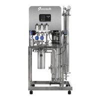
INSTRUCTION MANUAL ECOSOFT RO SYSTEM
MO6500BWTSS
8. CONTROLLER
8.2. INPUT & OUTPUT SPECIFICATIONS
Table 2. List of terminals
PURPOSE VOLTAGE MARKING PIN #
Power supply
Live
110-220 VAC,
50/60 Hz
L 32
Neutral N 31
Ground Ground 30
Input terminals
Conducvity meter Cond
1 — white
2 — black
Temperature sensor + Term −
3 — red
4 — green
5 — blue
Low feed pressure switch
5 V
(only use dry contact
NC/NO switches)
P_in 8–9
High operang pressure switch P_max 10–11
High permeate pressure switch P_perm 12–13
Permeate oat switch Level 14–15
Stop switch Stop 6–7
Output terminals
Pump contactor
110-220 VAC (matching
the power supply
voltage)
PUMP
28–29
27 (ground)
Alarm signal out ALARM 25–26
Entry electric valve Valve_IN
24 (neutral)
23 (open)
22 (ground)
Flush electric valve Valve_Rinse
21 (neutral)
20 (open)
19 (ground)
Bypass electric valve Valve_Bypass
18 (neutral)
17 (open)
16 (ground)
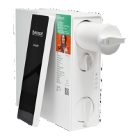
Ecoso OC5000 process controller is used for automang reverse osmosis system operaon. The
input and output device connecons are described in the table below.
Depending on current status and input device readings the controller will operate in any of the
following modes: Service, Standby, Forward Flush, Stop, Fault (described in the following secon).
The user interface comprises two buons and an LCD display. STOP buon is used for stopping
the unit (short press) or entering the Sengs menu (long hold). START buon is used for scrolling
in the Sengs menu or iniang a Forward Flush (if pressed during service screen display).
8.1. OVERVIEW
For more detail, please see the wiring diagram.