11
Installing the Motherboard
ATX1: ATX 20-pin Power Connector
Pin Signal Name Pin Signal Name
1 +3.3V 11 +3.3V
2 +3.3V 12 -12V
3 Ground 13 Ground
4 +5V 14 PS ON#
5 Ground 15 Ground
6 +5V 16 Ground
7 Ground 17 Ground
8 PWRGD 18 -5V
9 +5VSB 19 +5V
10 +12V 20 +5V
ATX2: ATX 12V Power Connector
Pin Signal Name
4 +12V
3 +12V
2 Ground
1 Ground
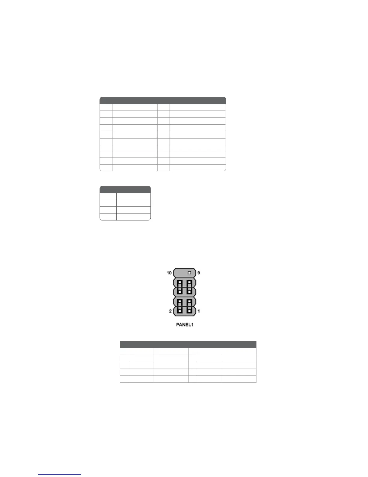
Front Panel Connector
The front panel connector (PANEL1) provides a standard set of switch and LED connec-
tors commonly found on ATX or micro-ATX cases. Refer to the table below for informa-
tion:
Pin Signal Function Pin Signal Function
1 HD_LED_P Hard disk LED+ 2 FP PWR/SLP *MSG LED+
3 HD_LED_N Hard disk LED-
5 RST_SW_N Reset Switch
7 RST_SW_P Reset Switch
9 RSVD Reserved
4 FP PWR/SLP *MSG LED-
6 PWR_SW_P Power Switch
8 PWR_SW_N Power Switch
10 Key No pin
* MSG LED (dual color or single color)
 Loading...