DIGITAL ECU TUNER 3 – User Manual
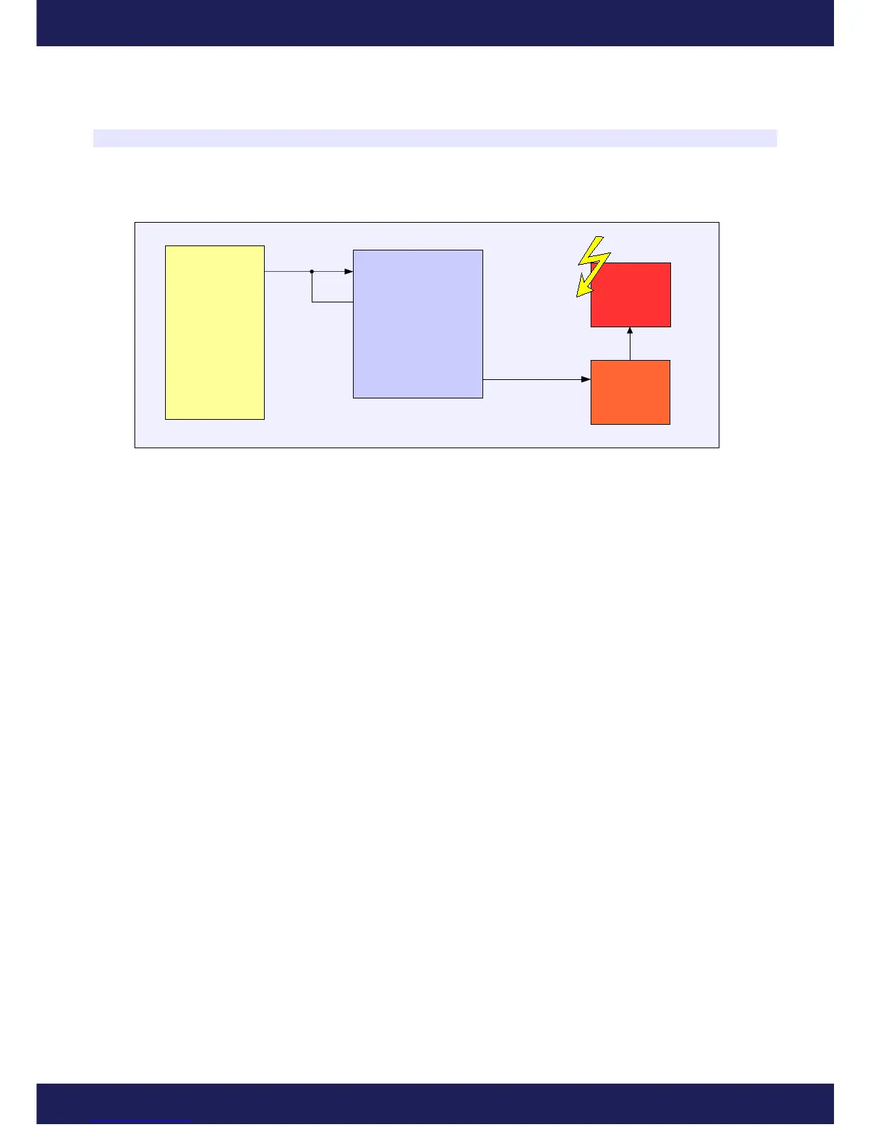
Ignition module
In case of modifications of the signal controlling the ignition module, the wiring diagram below should be used.
For this signal type, in the menu Setup/Ignition Configuration choose the Ignition Input Type: Hall Effect or
optical sensor. As the ignition mode choose the Retard single signal. This mode considers the coil dwell time and
copies it in the output signal.
Page 23
www.ecumaster.com
ECU
Ignition In (9)
Pullup(3)
DET 3
Ignition Out (6)
Ignition
Module
Ignition
Coil