xii
Figures
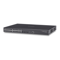
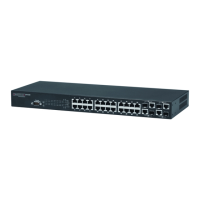
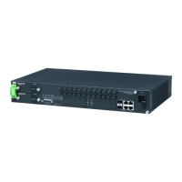
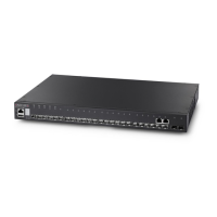
Figure 1-1 Front Panel 1-1
Figure 1-2 Rear Panel 1-1
Figure 1-3 Port and Power LEDs 1-3
Figure 1-4 Power Supply Socket 1-4
Figure 2-1 PoE Connections 2-2
Figure 2-2 Collapsed Backbone 2-3
Figure 2-3 Meeting Room 2-3
Figure 2-4 Making VLAN Connections 2-4
Figure 3-1 RJ-45 Connections 3-2
Figure 3-2 Attaching the Brackets 3-3
Figure 3-3 Installing the Switch in a Rack 3-4
Figure 3-4 Attaching the Adhesive Feet 3-4
Figure 3-5 Inserting an SFP Transceiver into a Slot 3-5
Figure 3-6 Power Socket 3-6
Figure 4-1 Making Twisted-Pair Connections 4-2
Figure 4-2 Wiring Closet Connections 4-3
Figure 4-3 Making Connections to SFP Transceivers 4-5
Figure B-1 RJ-45 Connector Pin Numbers B-1
Figure B-2 Straight-through Wiring B-2
Figure B-3 Crossover Wiring B-3
 Loading...