S149-01-880 Issue F
Page 4 © Edwards Limited 2011. All rights reserved.
Edwards and the Edwards logo are trademarks of Edwards Limited.
Introduction
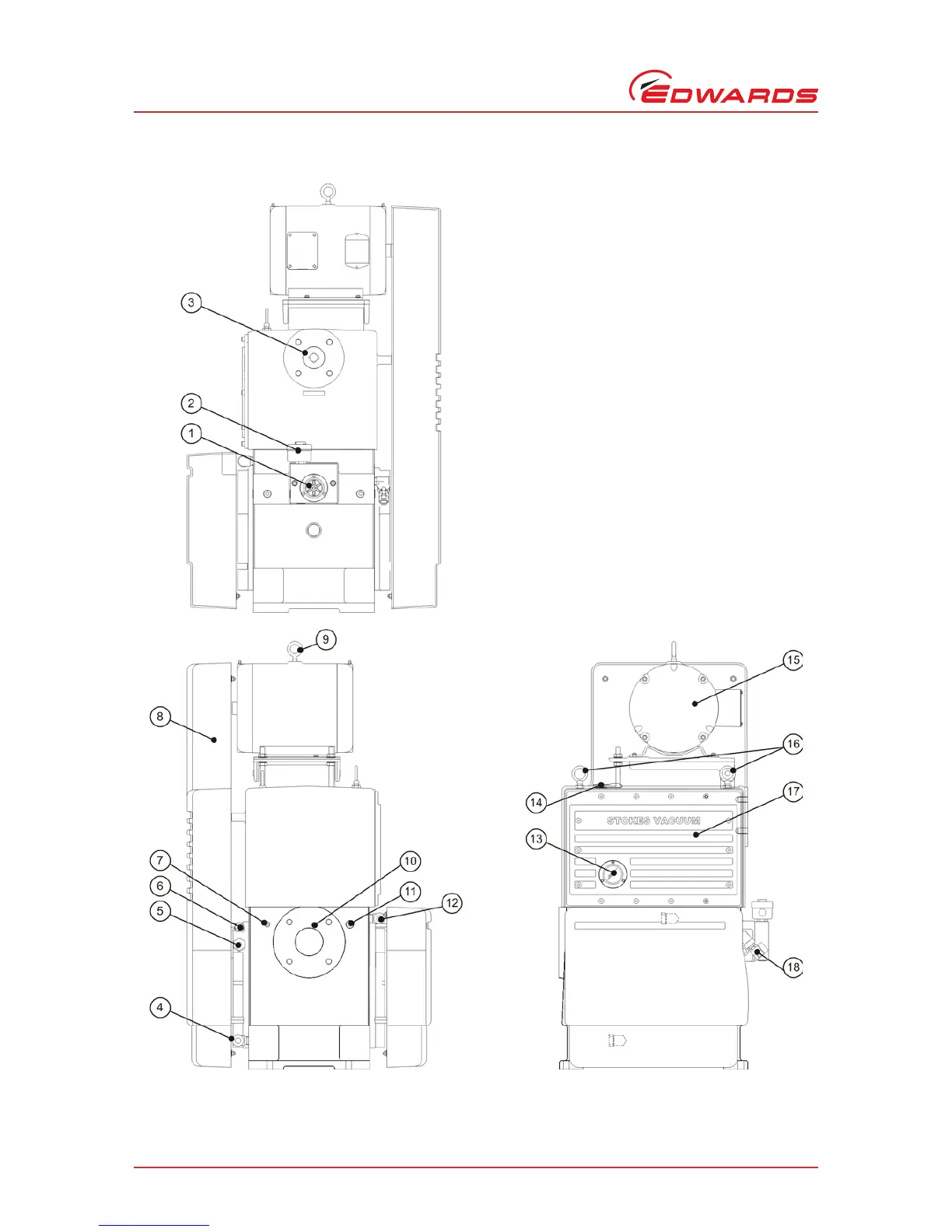
Figure 3 - 212-J pump general arrangement
1. Oil flow indicator
2. Solenoid valve
3. Vacuum exhaust connection
4. Water inlet connection
5. Gas ballast purge connection
6. Gas ballast adjustment
7. 1/4 inch vacuum access port
8. Belt guard
9. Motor lift eye-bolt
10.Vacuum inlet connection
11.1/2 inch vacuum access port
12.Water outlet connection
13.Oil level sight glass
14.Oil fill port
15.Motor
16.System lift eye-bolt
17.Reservoir cover
18.Oil drain valve