S149-01-880 Issue F
Page 2 © Edwards Limited 2011. All rights reserved.
Edwards and the Edwards logo are trademarks of Edwards Limited.
Introduction
1.2 ATEX directive implications
The Microvac pump is not designed to meet European ATEX requirements.
1.3 Description
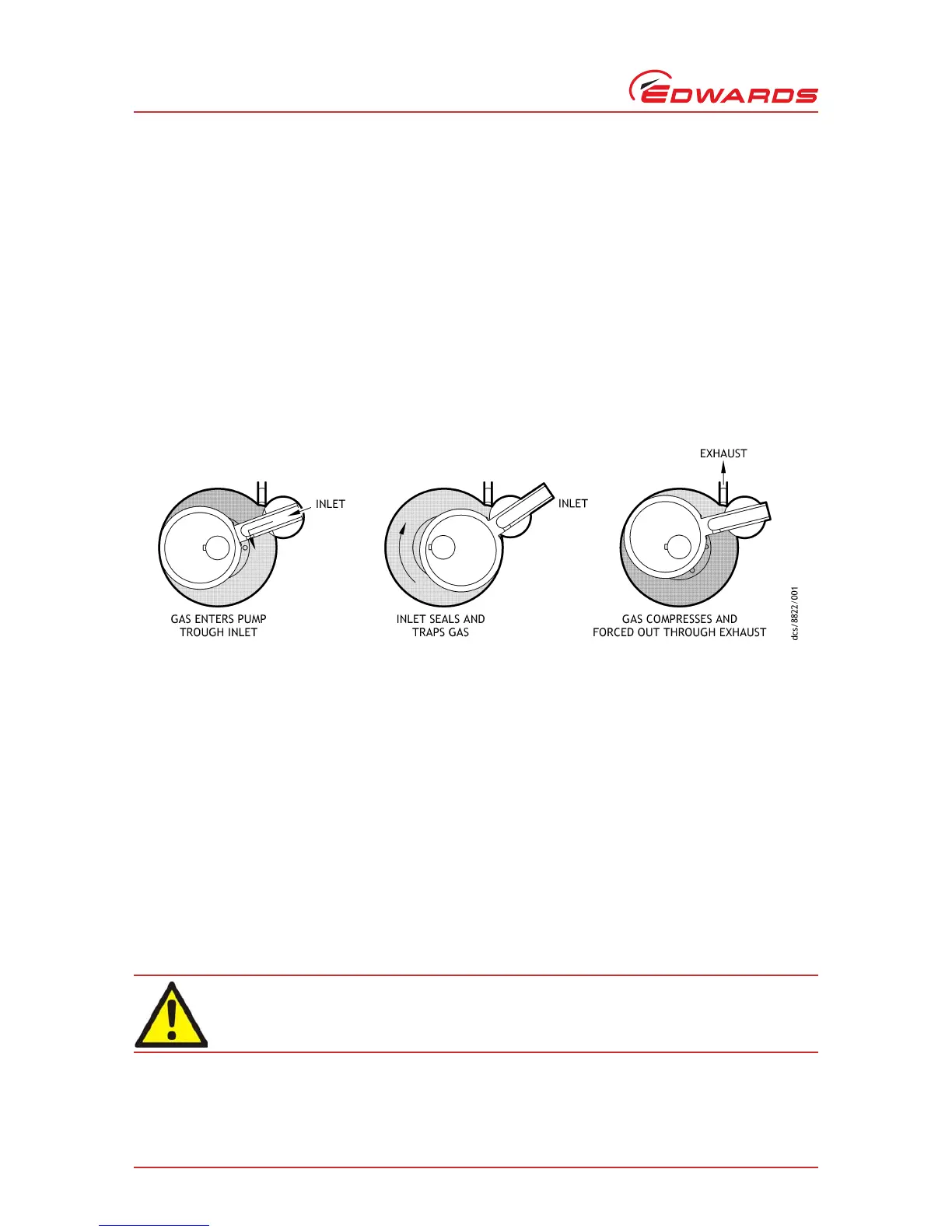
The Microvac pumps are self-contained, rotary, oil sealed piston type units. An eccentric mounted on the drive shaft
drives the piston. Two free-oscillating floating hinge bars in the pump housing guide the piston slide. The piston
assembly rotates clockwise when facing the drive end. Air enters the pump through the intake and passes through
the piston slide as the piston performs its intake stroke. As the piston nears the top center position the intake port
is closed, separating the system from the pump (see Figure 1). The air is entrapped on the front side of the piston as
it begins the next stroke. As the piston continues to rotate, the entrapped air is compressed and discharged through
the exhaust valves and out the reservoir exhaust outlet. The exhaust valves are a corrosion-resistant, heavy duty,
poppet type.
Figure 1 - Theory of operation
When the pump is in operation, lubrication of the internal parts is completely automatic. Oil is forced by atmospheric
pressure from the reservoir through internal oil passages to the shaft bearings. The oil is then fed into the pump to
provide the necessary piston-to-cylinder oil seal. The oil in the pumping chamber is forced out through the exhaust
valves with the compressed air and returns to the reservoir. A solenoid valve prevents oil from flooding the pump in
the event of a power failure or when the pump is shutdown without vacuum being broken.
The pump general arrangements are provided in Figures 2 through 4.
1.3.1 Gas ballast
To pump high vapor loads, gas ballast is delivered into the pump to prevent condensation of the vapor carried by the
pump gases.
Air can be introduced to the low vacuum stage. Alternatively, an inert gas such as nitrogen can be supplied through
a suitable external valve.
1.3.2 Water system
A cooling water supply rated at 30 °C (85 °F) and 3.8 LPM (1 GPM) for the 149-H/149-HS, 5.7 LPM (1.5 GPM) for the
212-J, and 7.6 LPM (2 GPM) for the 412-J maximum is required for efficient pump performance. Internal pump water
pressure should not exceed 35 psig (Refer to Section 3.8 for information).