CAUTION
DO NOT place heavy objects on the cables or bend them excessively. Support each cable so as
not to apply direct force to the connectors or terminals. If any problem occurs in cables, connectors
or terminals, the STP pump may not function normally. DO NOT apply voltage to each connector
pin and DO NOT cause any short-circuiting between pins. Install cables so that personnel are not
exposed to risk of tripping or falling.
CAUTION
DO NOT apply surge voltage exceeding 1 kV to the input power line. Always ground the power
cable to prevent electric shock.
Support each cable so as not to apply direct force to the connectors or terminals. Connect each
cable securely with caution, avoiding any obstacles as follows:
1. Connecting the STP connection cable
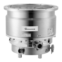
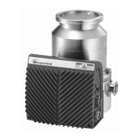
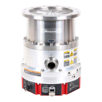
Connect the socket side of the STP connection cable to the STP connector of the STP pump and
connect the pin side to "P.CONNECTOR X1" of the STP control unit, and connect the plug (pin)
side "MOTOR X4" (equipped SCU-1600/1601), "P.CONNECTOR CON2" (SCU-350 series) on the
STP control unit.
2. Connecting the TMS connection cable (See STP Pump Instruction Manual (B) for use with the
TMS unit only)
Connect the pin side of the TMS connection cable to the "TMS X5" of the STP control unit.
3. Connecting the power (primary side) cable
Connect the power cable to the "AC POWER X2" or "AC POWER CON1" (SCU-350 series) on
the STP control unit rear panel.

 Loading...


