EasyManua.ls Logo

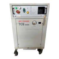
Edwards TCU 40/80

Edwards TCU 40/80
76 pages
To Next Page IconTo Next Page
To Previous Page IconTo Previous Page
Loading...
Table
14
-
Miscellaneous
fault
conditions
(continued)
Indicator
Remote
START/STOP
fail.
Hour
counter
fail.
Remote
setpoint
enable
fail.
Possible
causes
Refrigerant
leak.
Temperature
controller
parameters
are
not
set
to
factory
defaults.
Temperature
controller
is
not
functioning
properly.
J72J2
interface
connector
is
wired
incorrectly.
Remote
START/STOP
jumper
not
removed
Hour
counter
not
recording
operating
time.
Absence
of
24
VAC
supply
to
interface
connector
J72J2
or
interface
connector
is
wired
incorrectly.
Relay
board
failure
(CR14).
Temperature
controller
parameters
are
not
set
to
factory
defaults.
Temperature
controller
not
functioning
properly.
Action
Visually
check
for
signs
of
compressor
oil
on
the
base,
insulation,
around
the
compressor
service
valves,
and
on
all
refrigeration
pipework.
Use
a
halogen
leak detector
to
leak
check
all
accessible
refrigeration
pipework
and
the
compressor
service
valves.
If
compressor
oil
is
noted
or
a
leak
is
located
remove
all
power
to
the
unit
and
contact
an
Edwards
service
representative.
Verify
temperature
controller
PID
settings.
Refer
to
the
"Temperature
controller"
portion
of
the
System
Check
on
page
21.
Verify
that
the
OUT
2
lamp
on
the
front
of
the
temperature
controller
is
ON
when
the
unit
is
in
cooling
mode.
Replace
the
temperature
controller
if
necessary
(EHVI
part
no.
P43008000).
Verify
proper
wiring
of
connector
J72J2.
Refer
lo
the
"Remote
Interface
wiring
schematic
"
on page
56..
Verify
that
the
remote
START/STOP
jumper
located
across
terminal
TB1-I
on
terminal
block
TB1
is
removed.
To
do
this,
opening
of
the
electrical
drawer
is
necessary.
This
will
activate
the
drawer
interlock
switch
and
shut
the
TCU
40/80
down.
Notify
the
tool
operator
prior
to
opening
the
electrical
drawer.
Verify
24
VDC
across
the
wires
connected
to
the
hour
counter (wire
#28
and
wire
#29).
To
do
this,
removal
of
the
front
access
panel
is
necessary.
Replace
the
hour
counter
if
necessary
(EHVI
part
no.
P43144900).
Verify
the
host
24
VAC
supply
to
pin
3
and
pin
4
on
connector
J72J2.
Refer
to
the
"Remote
Interface
wiring
schematic"
on
page
S6..
Verify
that
the
remote
setpoint
enable
relay
(CR14)
is
on.
Verify
temperature
controller
PID
settings.
Refer
to
the
"Temperature
controller"
portion
of
the
System
Check
on
page
21..
Verify
temperature
controller
is
in
remote
mode.
The
AUX
lamp
on
the
front
of
the
controller
should
be
ON.
Replace
the
temperature
controller
if
necessary
(EHVI
part
no.
P43008000).
Hazard
Type
2
Type
2
Type
4
Type
3
Type
4
Type
4
Type
3
Type
4
Type
2
Type
4
50
TCU
40/80
Temperature
Control
Unit

Related product manuals