USV MT3200 Instruction manual
MT Series
Page 20 of 36
8.2 Communications connection of UPS
A convenient communications interface is available that facilitates data
exchange with the UPS.
The connection should only be made using the cables specified in the
“Accessories” chapter.
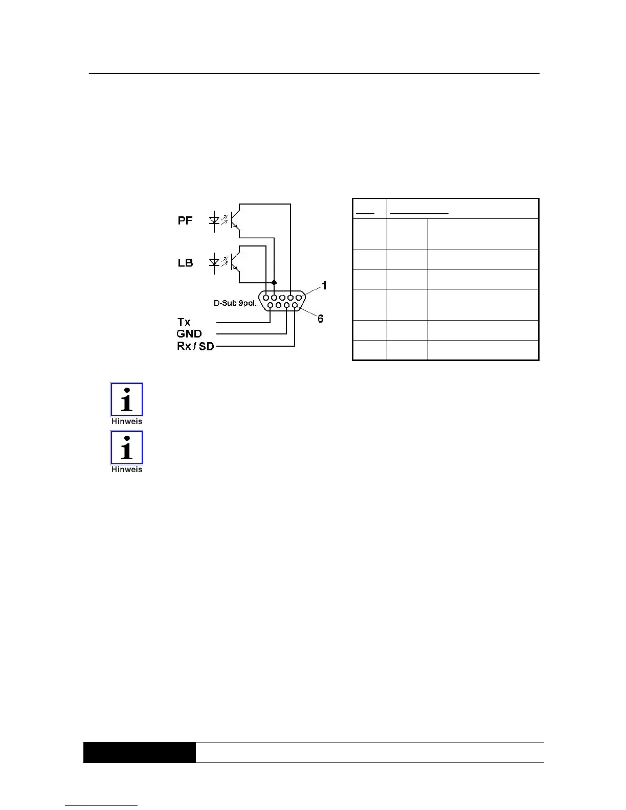
Fig. 6: Internal
wiring of UPS
communications
interface
Pin: Assignment:
2 LAN Signal: mains power
failure
4 LAN GND
5 LAN Signal: battery low
6 RS232 Receive data (Rx) or
shutdown (SD)
7 RS232 GND
9 RS232 Transmit data (Tx)
The communications interface is completely galvanically isolated.
The LAN signals have a shared earth which is not connected to the RS232
earth.
The UPS can also be forced to shut down immediately during support mode
via the RS232 serial interface. This is triggered via a permanent +12V signal
on receive data (Rx) (“shutdown” function).
8.3 Connection sequence
Connect the UPS to the mains making sure that the mains and UPS are safely
switched off beforehand.
Connect the consumer load(s) to the UPS. Ensure that all consumer loads are
switched off.
Connect the communication port with your host computer using the cable
supplied.