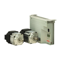
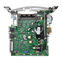
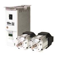
EFKA DA320G5351
33
Supplier Level
Code no. 311 with control operation
Code no. 3112 with control panel operation
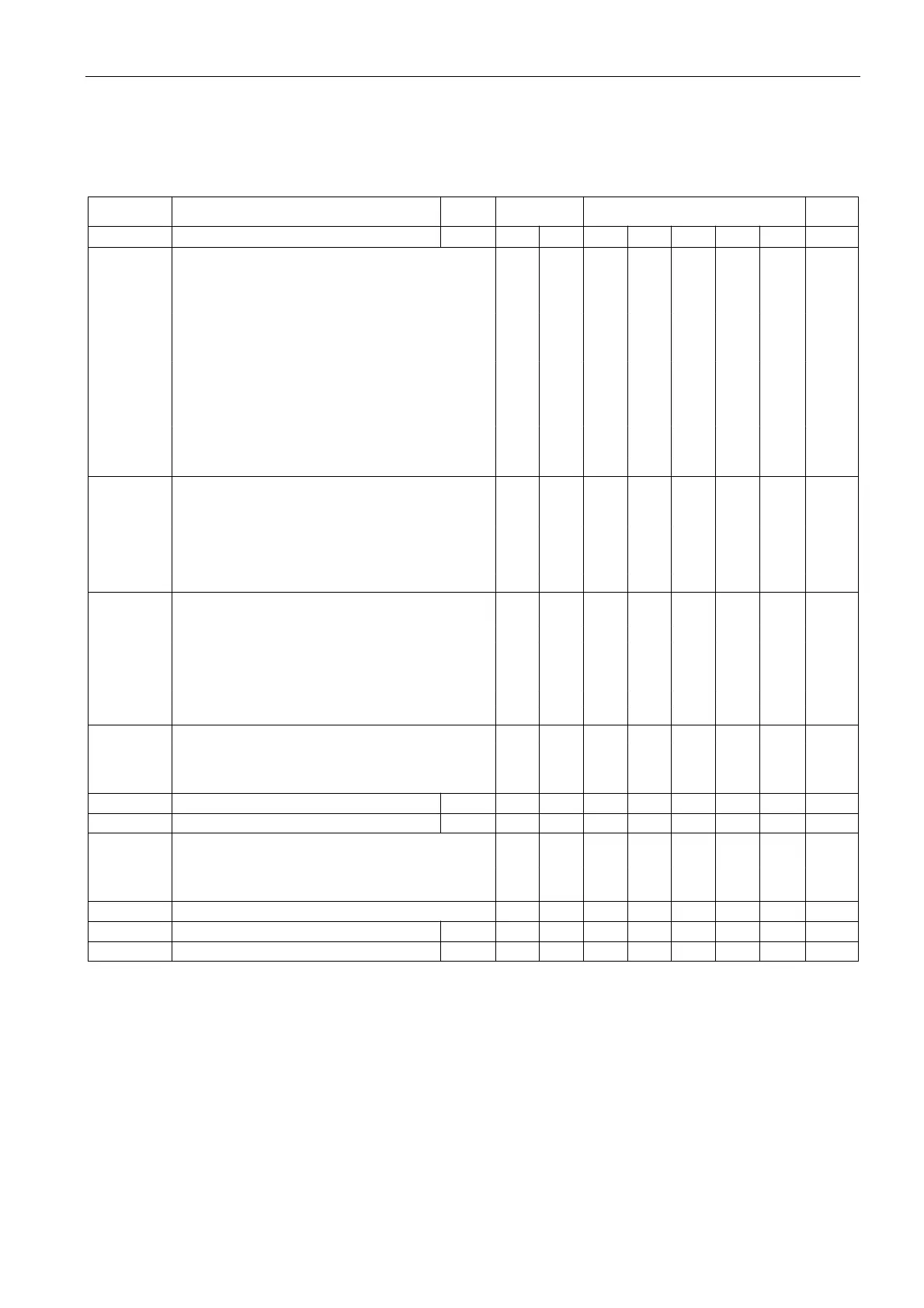
Parameter Designation Unit Limits Preset for Ind.
max min 100Ω 220Ω 680Ω 1000Ω
300 AA1 Selectable power transistors for signal A1 12 0 0 0 0 0 A
0 = No function
1 = Signal on output M1
2 = Signal on output M2
3 = Signal on output M3
4 = Signal on output M4
5 = Signal on output M5
6 = Signal on output M6
7 = Signal on output M7
8 = Signal on output M8
9 = Signal on output M9
10 = Signal on output M10
11 = Signal on output M11
12 = Signal on output VR
301 So1 Issue signal A1 3 0 0 0 0 0 A
0 = Signal until seam end (according to setting of
parameter 320)
1 = Signal over time
2 = Signal until seam end and drive stops
3 = Signal during stitch counting (according to
setting of parameter 309)
302 tr1 Starting point for signal A1 3 0 0 0 0 0 A
0 = Start at the beginning of the seam
1 = Start of the signal triggered by light barrier
sensing
2 = Start of the signal when the drive stops at the
seam end
3 = Start from light barrier covered onwards at the
beginning of the seam
303 do1 Delay of signal A1 2 0 1 1 1 1 A
0 = No delay until signal On
1 = Delay over time until signal On
2 = Delay over stitches until signal On
304 dt1 Delay time until signal A1 On ms 2550 0 0 0 0 0 A**)
305 St1 ON period of signal A1 ms 2550 0 0 0 0 0 A**)
306 nA1 Speed mode when signal A1 is On 2 0 0 0 0 0 A
0 = Pedal controlled speed
1 = Limited speed n9
2 = Limited speed n11
307 A1 Signal A1 On/Off 1 0 0 0 0 0 A
308 dA1 Stitches delaying signal A1 stitches 999 0 0 0 0 0 A
309 cA1 Stitch counting during signal A1 stitches 999 0 0 0 0 0 A
**) When programming the 3-digit or 4-digit control parameter values (without control panel), the 2-digit or 3-digit
value displayed must be multiplied by 10.
 Loading...