GB
- 11 -
Wear ear-muff s.
The impact of noise can cause damage to hea-
ring.
Keep the noise emissions and vibrations to a
minimum.
•
Only use appliances which are in perfect wor-
king order.
•
Service and clean the appliance regularly.
•
Adapt your working style to suit the appliance.
•
Do not overload the appliance.
•
Have the appliance serviced whenever ne-
cessary.
•
Switch the appliance off when it is not in use.
Caution!
Residual risks
Even if you use this electric power tool in
accordance with instructions, certain resi-
dual risks cannot be rules out. The following
hazards may arise in connection with the
equipment’s construction and layout:
1. Lung damage if no suitable protective dust
mask is used.
2. Damage to hearing if no suitable ear protec-
tion is used.
3. Health damage caused by hand-arm vib-
rations if the equipment is used over a pro-
longed period or is not properly guided and
maintained.
5. Before using the equipment
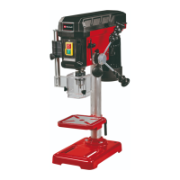
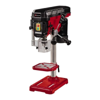
5.1. Assembling the machine (Fig. 1/3/4/5)
•
Place the base plate (1) in the desired posi-
tion.
•
Fasten the pillar (2) with flange using the sup-
plied screws (3).
•
Insert the screw gear in the drill table support.
•
Then insert the gear rack (30) in the drill table
support (5) with the teeth facing the screw
gear (identical projection).
•
Now slip these parts together over the pillar
(2). In doing so, make sure that the gear rack
is correctly seated in the teeth of the screw
gear.
•
To secure the gear rack at the top end, slip
on the guide sleeve (29) over the pillar and
fasten with the grub screw (20).
•
You can now fit the table and clamp in place
with the clamping lever. Following this, fit the
crank (27) and fasten tightly with the screw
(28).
•
Finally, fit the complete bit head to the pillar.
Align the head so that it is horizontal to the
base plate and fasten it in position with the
screws (33).
•
Screw the 3 supplied handles (9) in the hand-
le mounts.
•
Before you mount the drill chuck with the
MK shank, check that both parts are clean.
Insert the taper mandrel in the taper of the
drill chuck with a powerful jolt. Then insert the
taper in the spindle (Fig. 12)
•
Check the tension of the V-belt regularly befo-
re use (Fig. 8).
Important: All bare parts are greased in order to
protect them from corrosion. Before mounting the
drill chuck (10) onto the spindle (11), both parts
must be completely degreased using an environ-
mentally friendly solvent. This ensures optimal
transmission of power.
5.2 Installing the machine (Figs. 3/4)
Before you use the drill for the fi rst time it must be
mounted in a stationary position on a fi rm surface.
Use both mounting holes (12) in the base plate to
do this. Ensure that the machine is freely acces-
sible for operation, adjustment and maintenance.
Important: The fi xing screws may only be tighte-
ned to a point where they do not distort or deform
the base plate. Excessive tension can lead to
fracture.
5.3 Hinged chip guard (Fig. 5)
Unscrew the three screws (21).
Push the transparent cover (23) into the groove
of the red mounting frame (24) and fasten it again
with the screws (21).
The height of the cover (23) is infi nitely adjustable
and can be locked using both thumb screws (22).
The chip guard (13) can be fl ipped upwards to
change drill bits, however ensure that the chip
guard (13) is back in its initial position before rest-
arting the equipment.
5.4 Prior to starting
Ensure that the voltage of the mains supply com-
plies with the specifi cations on the rating plate.
Connect the machine only to a socket with the
properly installed earthing contact.
The table drill is equipped with a no-volt trip that is
designed to protect the operator from an undesi-
red restart following a drop in voltage. Should this
occur, the machine must be manually restarted.
Anl_TC_BD_630_EX_PH_SPK7.indb 11Anl_TC_BD_630_EX_PH_SPK7.indb 11 28.10.2020 13:30:5328.10.2020 13:30:53