ELAN HOME SYSTEMS
© ELAN Home Systems 2005 • All rights reserved. Page 15
A1240 INSTALLATION MANUAL
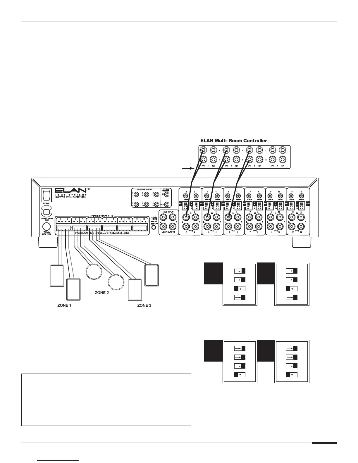
Direct Input Bussing
There are independent Direct Input Bus DIP switches for each channel on the A1240. These
DIP switches are located directly below the BUS L/R DIP switches and are labeled 1-12.
Their purpose is to allow the creation of summed mono signals without having to use addi-
tional patch cables. For example, if A1240 Input #1 is being fed a monaural signal, and Input
#2 needs to receive that same signal, slide the DIP switch labeled “1” to the left, (ON) position
for both channels 1 and 2. Direct Input Bussing is for channel pairs only (1/2, 3/4, 5/6, 7/8,
9/10, 11/12). In other words, Channel 3 can only be sent to Channel 4, and Channel 4 can only
be sent to Channel 3.
ZONE OUTPUTS
RCA ‘Y’
Cables
BUS
BUS DIP Switch Settings-Right Input
CH 1, 3, 5
CH 2, 4, 6
BUS
BUS DIP Switch Settings-Left Input (as shown)
CH 1, 3, 5
CH 2, 4, 6
OR
ELAN Multi-Room System w/ Direct Input
Bussed Mono Zones
• ELAN Multi-Room Controller Zone Outputs 1-3 to A1240
Inputs 1, 3, & 5 OR Inputs 2, 4, & 6 Using RCA 'Y' Cables
Each Zone's Speakers Have Independent Volume
ELAN Multi-Room System w/ Direct Input Bussed Zones
The example below shows the use of the Left (odd numbered) inputs. The Right (even-
numbered) inputs can also be used. Make sure to set the DIP switches correctly, as shown
below, depending on whether Right or Left inputs are being utilized.