7
7EN
ELDES GATE CONTROLLER ESIM120/320 User Manual v.1.1
LED Indicator Functionality
SIM STAT indication SIM card status
OFF No mains power / Successfully connected to GSM/3G network
Steady ON SIM card is attempting to connect to the GSM/3G network / SIM card is not present / PIN code
enabled
NETW indication Signal strength
OFF No GSM/3G signal
Flashing every 1 sec. Poor
Flashing several times per sec. Medium
Steady ON Excellent
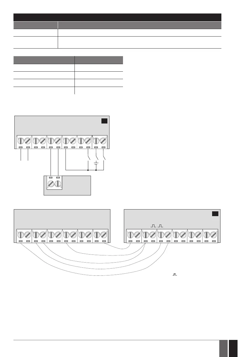
2.3. Wiring Diagrams
General wiring
ESIM120/ESIM320
AC/DC
Power
supply
GATE
AUTOMATION
DEVICE
RELAY2RELAY1 COM Z3 Z2 Z1
+
-
2
Example of ESIM120/ESIM320 system wiring to gate automation device
FO Fault output; open
collector type
+24V Power supply
output for powering
aux. equipment
Pulse input
GND Common terminal
ESIM120/ESIM320 GATE AUTOMATION DEVICE
AC/DC RELAY1 RELAY2 COM Z5 Z4 Z3 Z2 Z1 F0 +24vGND
3