3
ARCHIMEDE LCD SERIES - ENG
ELECTROIL
1. SPECIFICATIONS
With this manual, we would like to give you the most important information about the correct use and maintenance
of the inverter.
The devices described in this manual are:
IMMP1.1W-BC: Single-phase Inverter for single-phase motor pump, max 1.1 kW (1.5 Hp), 9Ampere, with LCD
16x2 display and Blue Connect radio communication;
IMMP1.8W-BC: Single-phase Inverter for single-phase motor pump, max 1.8 kW (2.5 Hp), 13 Ampere, with LCD
16x2 display and Blue Connect radio communication;
IMMP2.2W-BC: Single-phase Inverter for single-phase motor pump, max 2.2 kW (3 Hp), 15.5 Ampere, with LCD
16x2 display and Blue Connect radio communication;
IMTP1.5W-BC Single-phase Inverter for three-phase motor pump, max 1.5 kW (2 Hp), 7Ampere, with LCD and
Blue Connect radio communication;
IMTP2.2W-BC: Single-phase Inverter for three-phase motor pump, max 2.2 kW (3 Hp), 9.5 Ampere, with LCD
and Blue-Connect radio communication system
ITTP1.5W-BC: Three-phase Inverter for three-phase motor pump, max 1.5 kW (2 Hp), 4 Ampere, with LCD and
Blue-Connect radio communication system
ITTP2.2W-BC: Three-phase Inverter for three-phase motor pump, max 2.2 kW (3 Hp), 5.5 Ampere, with LCD
and Blue-Connect radio communication system
ITTP3.0W-BC: Three-phase Inverter for three-phase motor pump, max 3.0 kW (4 Hp), 7.5 Ampere, with LCD
and Blue-Connect radio communication system.
These inverters are devices specially designed for pump motor control,
thanks to a perfect feed-back pressure: it assures a good energy saving
and it has many programmable functions, that are not in the other
common directly supplied motor pumps. All models have a servo-
ventilation cooling, controlled by the inverter temperature. The following
instructions and rules about the standard configuration are as follows.
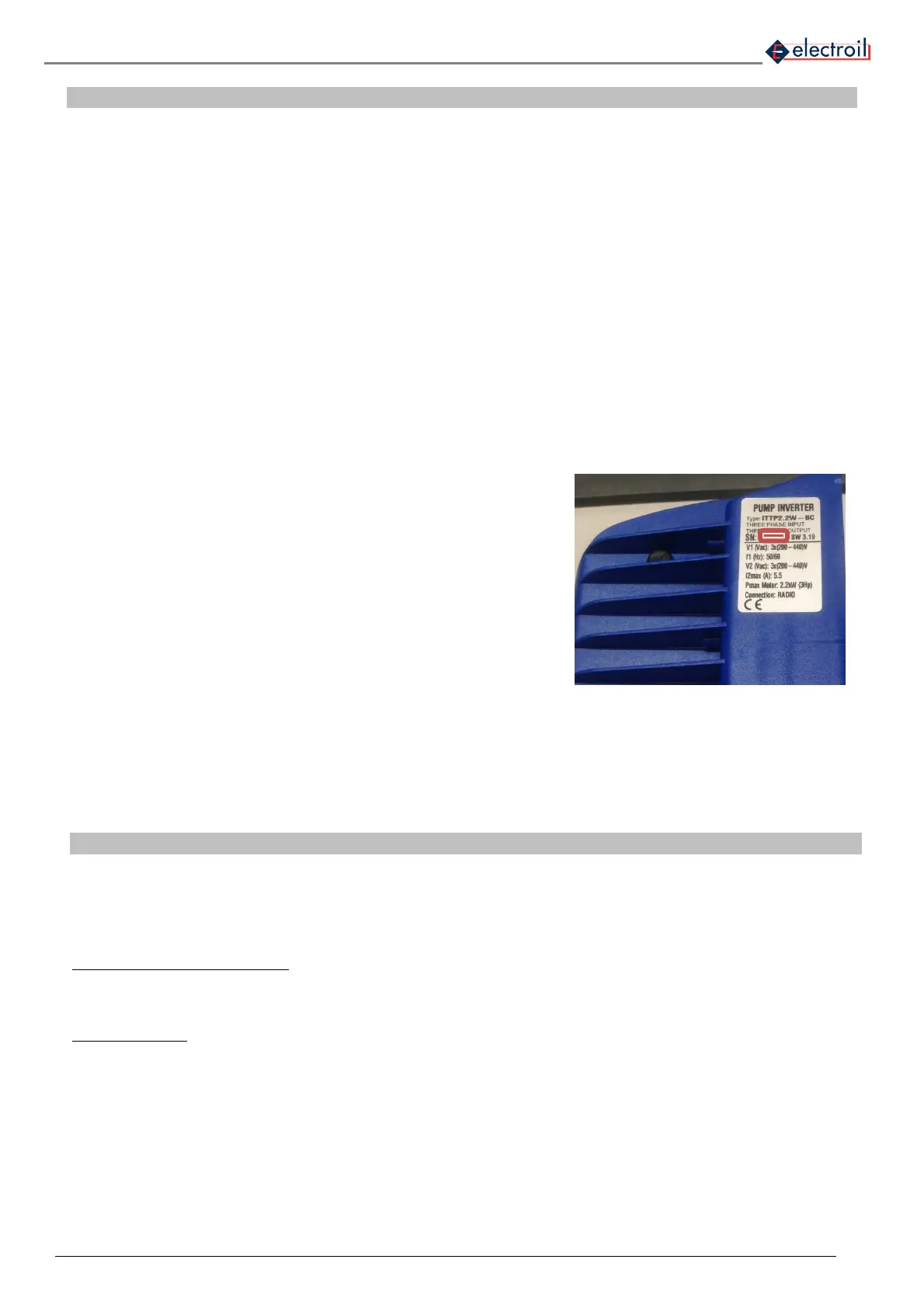
If you require technical assistance regarding specific parts at Service
Sales please do specify the exact name of the model, printed on the
label, the serial production number on the upper-left part of the product
(fig. 1), and the software version, reading the two numbers showed on
the led bar, switching-on the input supply line.
2. WORKING OPERATIONS
This Pump–Inverter system is made up by a centrifugal pump that is moved by an asynchronous motor. This system
has to keep the pressure steady, independently from the flow (consistent with the maximum load applicable to the
motor, otherwise the maximum current absorption).
The output pressure is monitored by a pressure transducer with 4-20mA. The control logic works with an output of
15V that supplies the pressure transducer.
CLOSED OUTPUT WORKING: to prevent a closed output working, the control logic read the motor’s working point
on respect to the curve saved during the check with closed delivery; if this point is under the checked curve value,
the system switches off the pump, and an information appears on display. At the end of this condition, the system
restarts its normal operation.
DRY WORKING: to prevent the pump from working when there is a suction condition problem, caused by an
insufficient inlet flow, the system calculate an algorithm with the pressure, the motor power and power factor, and if
the value is under a minimum value , it switches off the pump, and an advise appears on display.
The motor pump electric protection is controlled by the limitation of the current absorption (programmable). When
the current protection is on, an alarm appears on display. When the condition disappear, the system restart with the
normal functioning.
Figure 1: serial number of the inverter