4
ARCHIMEDE LCD SERIES - ENG
ELECTROIL
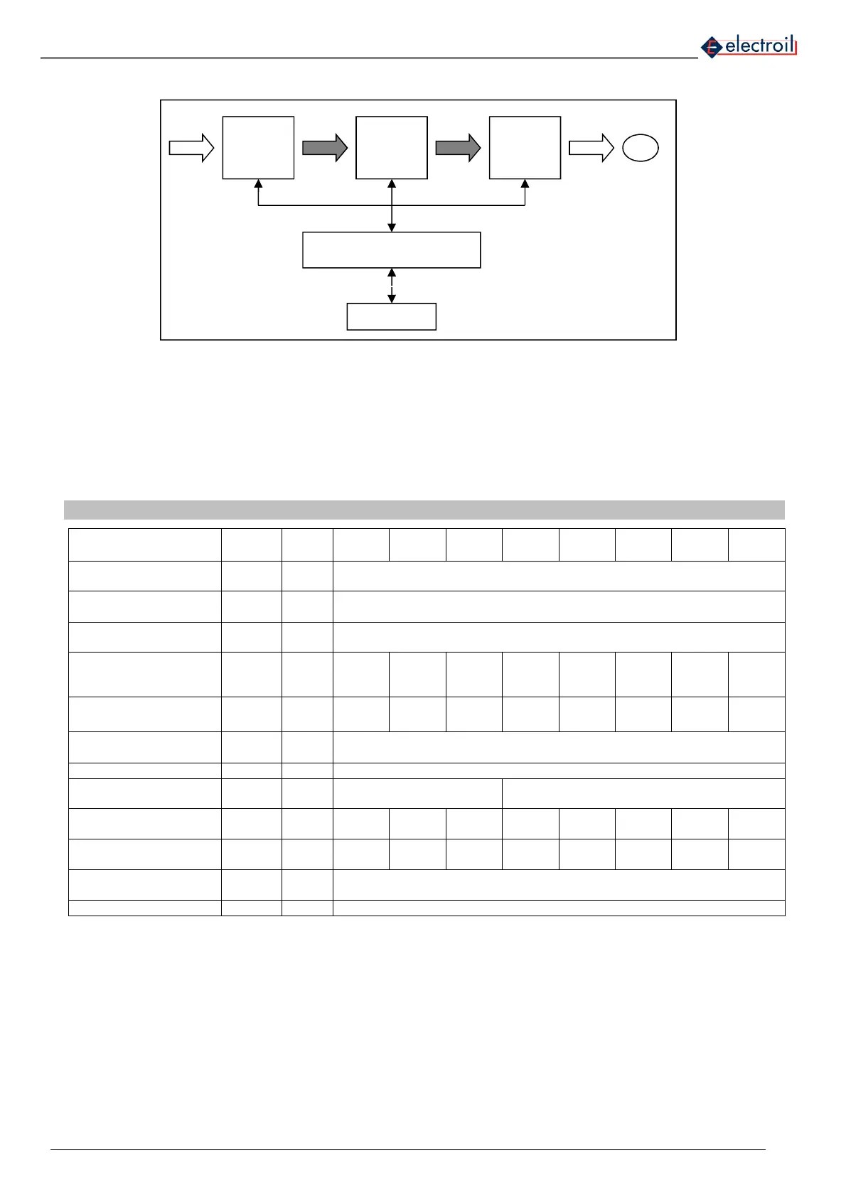
2.1 Structure of a frequency converter
Figure 2: structure of a frequency converter
a.c. Alternative Current
c.c. Direct current
Rec Rectifier
INT IGBT intermediate driver circuit
3. WORKING CONDITIONS
Meas.
Unit
IMMP1.1
W-BC
IMMP1.8
W -BC
IMMP2.2
W-BC
IMTP1.5
W –BC
IMTP2.2
W-BC
ITTP1.5
W-BC
ITTP2.2
W-BC
ITTP3.0
W-BC
Ambient working
temperature
T
amb
°C 0..40
Maximum relative
humidity
%
(40°C)
50
Protection grade of the
Inverter
IP 55
Nominal motor power
connected to the
Inverter
P
2n
W
Hp
1.1
1.5
1.8
2.5
2.2
3
1.5
2
2.2
3
1.5
2
2.2
3
3.0
4
Nominal input voltage
supply of the Inverter
V
1n
V
1x
210-244
1x
210-244
1x
210-244
1x
100-244
1x
100..244
3x
200..440
3x
200..440
3x
200..440
Frequency voltage
supply Inverter
f
1
Hz 50-60
Voltage Inverter output V
2
V = V
1n
Fequency Inverter
Output
f
2
Hz 50-60 0..140
Nominal input current
RMS
I
1n
A 11 15 19 12 14 5 6.5 8.5
Nominal output current
(to motor)
I
2n
A
Maximum output
current (duty=100%)
I
2
A I
2n
+ 5%
Storage temperature T
stock
°C -10..+50
Table 1: Working conditions
• Vibrations and hits: they must be avoided by a correct assembling;
• For different environment conditions, please contact our Sales Department.
REC
INT
INV
CONT
TRANSM
1 x 230V/
3 x 400V
1 x 230V
or
3 x 230V
or
3 x 400V
c.c.
c.c.
a.c.
M Motor
Cont Control logic by micro-processor
Transm Transmission line to ext.
Inv IGBT bridge three-phase inverter
 Loading...