9
ARCHIMEDE LCD SERIES - ENG
ELECTROIL
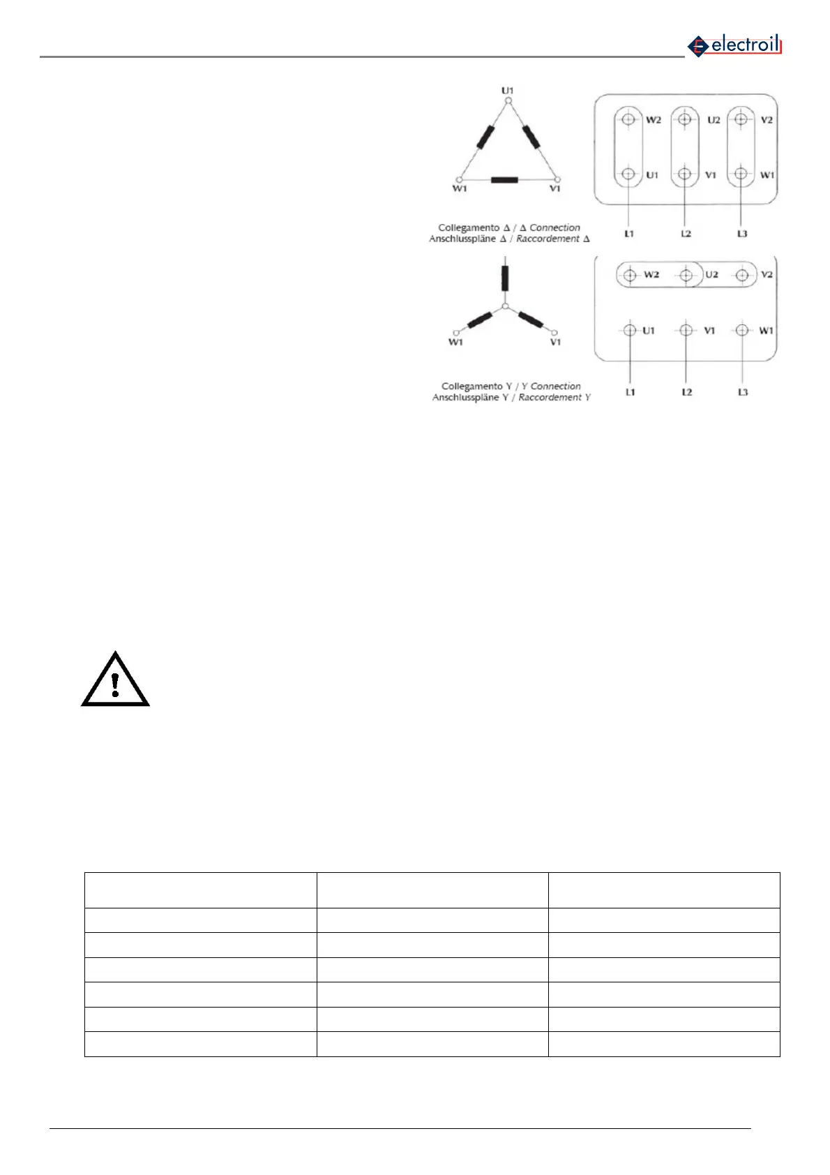
The single-phase input / three-phase output inverter
(IMTP) must be installed on asynchronous three-phase
motor with 100-240Vac 50/60 Hz voltage supply.
Phases must be configured to delta mode if the motor
is 230V ∆ / 400V λ (most common case, as in Figure
12).
Figure 12 – Delta motor phases connection
The three-phase input / three phase output inverter
(ITTP) must be installed on asynchronous three-phase
motor with 200-460 Vac 50/60 Hz voltage supply. The
phases must be connected in star mode if the motor is
230V ∆ / 400 V λ (most common case, as in Fig 13).
Figure 13 – Star motor phases connection
The unit is equipped with output over-current protection;
it is not necessary to install any additional safety device
between the inverter and the pump in order to protect
the motor in case of failure.
Do connect the cable of the Inverter (No. 2 of fig. 3) to the power plug of the pump.
Make sure the pump is in accordance with the operating conditions listed in Chapter 3 of this handbook. The pump to
function with this Inverter, if it’s single-phase type, must have the appropriate capacitor for the auxiliary winding and
connected to power cable properly dimensioned, with a plug (schuko recommended).
For submersible motor pump with a cable length more than 20 meters be sure that the motor-pump is designed to
works with inverter (may have a good phase-phase electrical insulation and not conductive rolling bearings) otherwise
you need to use the specific output filter (optional – ask our sales service) connecting it between the inverter output
and the motor pump voltage supply cable.
WARNING: : it is not possible to use an additional starting capacitor with circuit breaker; if the motor already
has this type of capacitor wired, it must be disconnected, and the pump will start normally through the
inverter and only the capacitor operating in permanent mode.
5.4 Inverter-Line connections
The line voltage supply must match with the Inverter limits, described on chapter 3 – WORKING
CONDITIONS. Do ensure proper protection from general electrical short circuit on the line.
The plant to which the inverter is connected must be conforms to safety regulations in use:
• Differential automatic switch with I∆n = 30mA: the correct switch is the A or B type (recommended B type), able to
recognize leakage currents with pulse components and direct components, immune to the electromagnetic interferences
typical of the inverters and cut-wave electronic rectifiers.
• Magnetic-thermal automatic switch with intervention current proportionate to the power of the pump installed (see
Table 2)
• Ground connection with total resistance less than 100 Ω
• If required by local electrical regulations in force, the installation of a differential circuit breaker, make sure it is of a
type suitable for installation (see table below). The switches are suitable for those with the characteristic curve for
alternating-current fault.
Pump power kW
Magneto-thermal protection (A)
on single-phase 230V version
Magneto-thermal protection (A)
on three-phase 400V version
0.5 (0.75 Hp) 6 6
0.75 (1 Hp) 10 6
1.1 (1.5 Hp) 16 10
1.5 (2 Hp) 20 10
2.2 (3Hp) 25 16
3.0 (4 Hp) - 20
Table 2: Magneto-Thermal protections suggested