13
ARCHIMEDE LCD SERIES - ENG
ELECTROIL
• At the end of the check the pump will work normally.
• Regulate the desired pressure value directly pressing buttons + or -, during pump working.
We suggest to use the ACCURATE CHECK specially for single-phase pumps, Jet, self-priming and periferical
types.
6.3 User’s check after Inverter setting
Check the pump stop to output closed: At the first installation open the output on the pump flow, press START,
wait a few seconds for the plant go to pressure set, then close the output flow (slowly) and make sure that the motor
stops (after a few seconds) showing on display "MINIMUM FLOW". In case the motor doesn’t stop you must select
MOTOR DATA - POWER STOP and set a higher value than the default (102%) set by the constructor. The absolute
stop power value is presented at regular times on display at the top-central position (see fig. 17).
Check pump dry-working: After installing, if is possible, close the suction/intake line in order to simulate a dry run
situation of the pump and check that, after approximately 40 seconds (or the delay time setting), the pump stop and
the display show the message “DRY WORKING”. If, after this time, the pump does not stop, you must enter into
MOTOR DATA and set a higher value of DRY WORKING STOP POWER (default 80%), otherwise enter on
ADVANCED FUNCTIONS – PRESSURE CONTROL setting a higher value of the parameter COSFI LIMIT (by
default set to 0.50). Save data after modifying.
6.4 Programming Functions
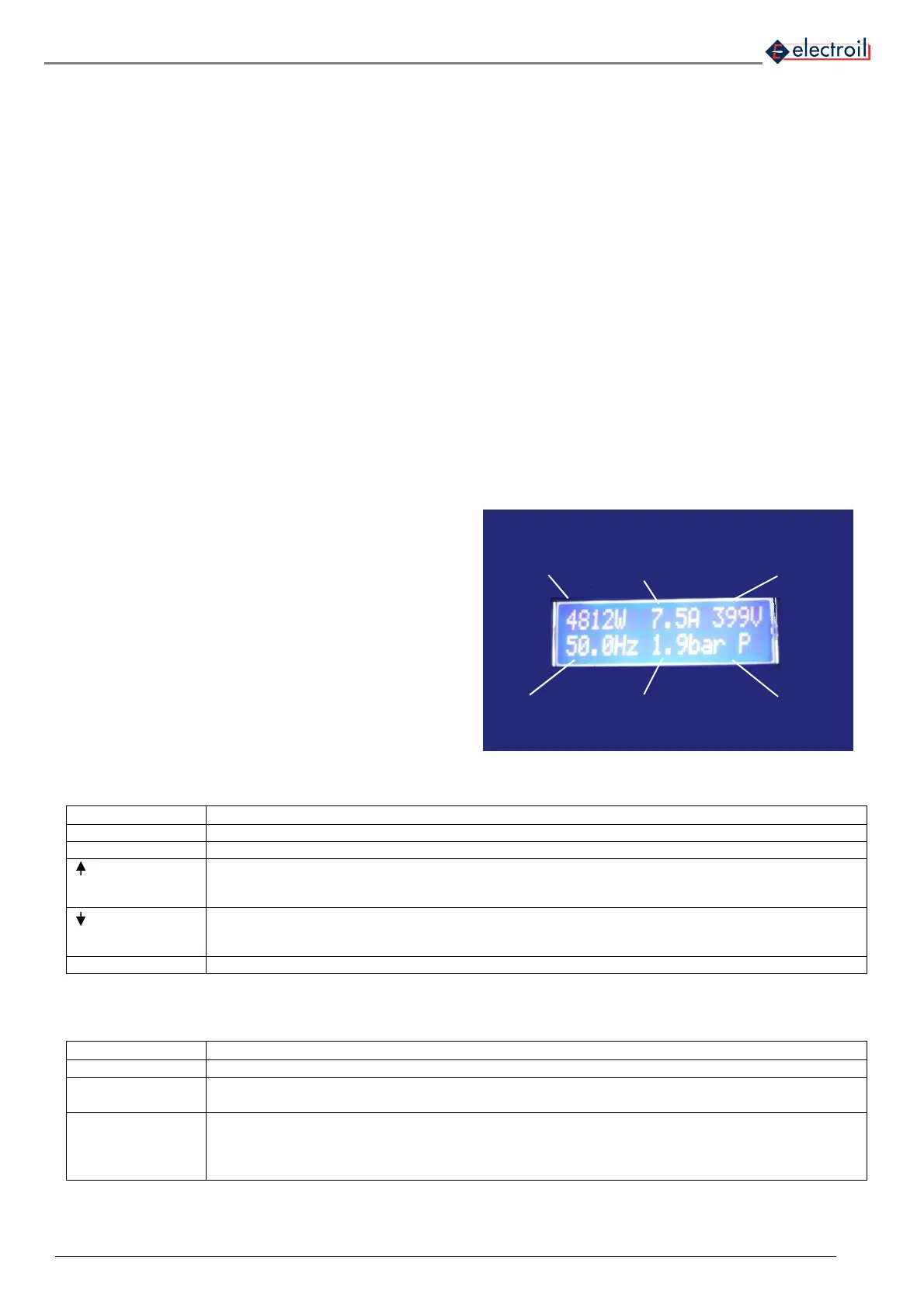
• Display:
Figure 17: LCD Display data
• List of command on the control panel
FUN To enter on main functions menu
START/ENTER Pump start / To enter on the function and modify the values
+ It allows scrolling up the items on the menu or positive change in the value of variables; after the
variation press ENTER.
Encrease the reference pressure during functioning.
- It allows scrolling down the items on the menu or negative change in the value of variables; after the
variation press ENTER.
Decrease the reference pressure during functioning.
STOP/ESC Pump stop / To exit to the function and automatically saving
Table 3: List of commands on the control panel
• LED description
Power ON
• Green fixed: input voltage supply ON
Motor ON
• Green fixed: Motor running;
• Green flashing: before stopping for minimum flow
Alarm
• Red fixed: Alarm (see Alarm list – table 7). Require manually re-start (STOP+START)
• Red flashing high frequency: Alarm and motor stop with automatic re-start;
• Red flashing low frequency: Problem at the pressure sensor on group functioning – without
stopping pump
Table 4: Led description
INVERTER
POWER
ABSORBING
CURRENT ABSORBING
POWER FACTOR (PF)
MINIMUM FLOW STOP
/ INVERTER
TEMPERATURE
FREQUENCY
DELIVERY PRESSURE
PUMP (P) / MASTER-SLAVE
(C0, C1, ..)