22
8.6 Three-Phase Asynchronous
Motor – Inverter
8.6.1 Motor Characteristics
Three-Phase power is fed
by the inverter. The phase
shift between the phases is
120° and peak amplitude is
310 V.
It is possible to get an
idea of the efficiency of the
motor by measuring the
resistance of the coils:
Terminal 1 and 2: 3 Ω to 6 Ω
Terminal 2 and 3: 3 Ω to 6 Ω
Terminal 3 and 1: 3 Ω to 6 Ω
Component Specifications
S. No. Component Specifications
1 Motor
200 V, 4 A, 330 Hz (Max.),
RPM (Max.)-18,600, Insulation
Class-F
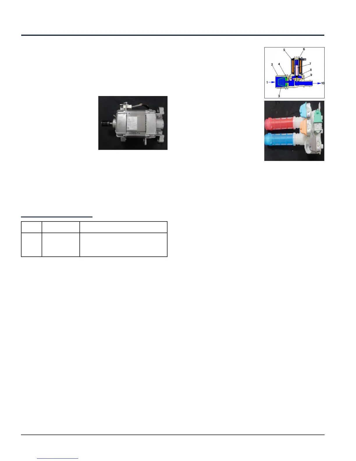
8.7 Solenoid Valves
• Any work on electrical Appliances must only be
carried out by qualified personnel.
• Unplug the Appliance before accessing internal
components.
• After disconnecting the plug from the socket, wait
about 2 minutes before removing the MCB plastic
cover, thus allowing any condensers to discharge
and avoid an electric shock.
87.1 General Characteristics
This component introduces water into the detergent
dispenser and is controlled electrically by the Main
Control Board via TRIAC. The level of water in the tub
is controlled by the Analog Pressure Sensor.
1. Water inlet
2. Solenoid valve body
3. Filter or needle trap
4. Flow reducer
5. Coil
6. Spring
7. Moving core
8. Rubber
9. Membrane
10. Water outlet
8.7.2 Operating Principle
When idle, the core pushed by a spring keeps the
central hole of the membrane closed and so the
latter hermetically seals the access to the water
in inlet duct. When the coil is powered, the core is
attracted, releasing the central hole of the membrane.
Consequently, the valve opens.
8.7.3 Mechanical Jamming of the
Solenoid Valve
The Solenoid Valve may jam or open without being
actuated (which will cause flooding if the Pressure
Sensor controlling the water level does not trip). If
this occurs, the Electronic Control System (which
continuously monitors the flow sensor) will lock the
door, start the Drain Pump and display an Error
simultaneously.
8.7.4 Low Water Pressure
The Flow Sensor may not generate a signal during the
water fill phases, even though power is being supplied
to the Solenoid Valve. This condition may result due to
a closed water tap or clogged filter on the Solenoid
Valve (with ensuing low water pressure). If this occurs,
only a WARNING will be displayed and the cycle will
continue for 5 minutes, after which an Error will be
signalled.
Electrical Components – EFLS617SIW / EFLS517SIW / EFLS417SIW